Jump to the content of the page

Load cells

Download
Load range
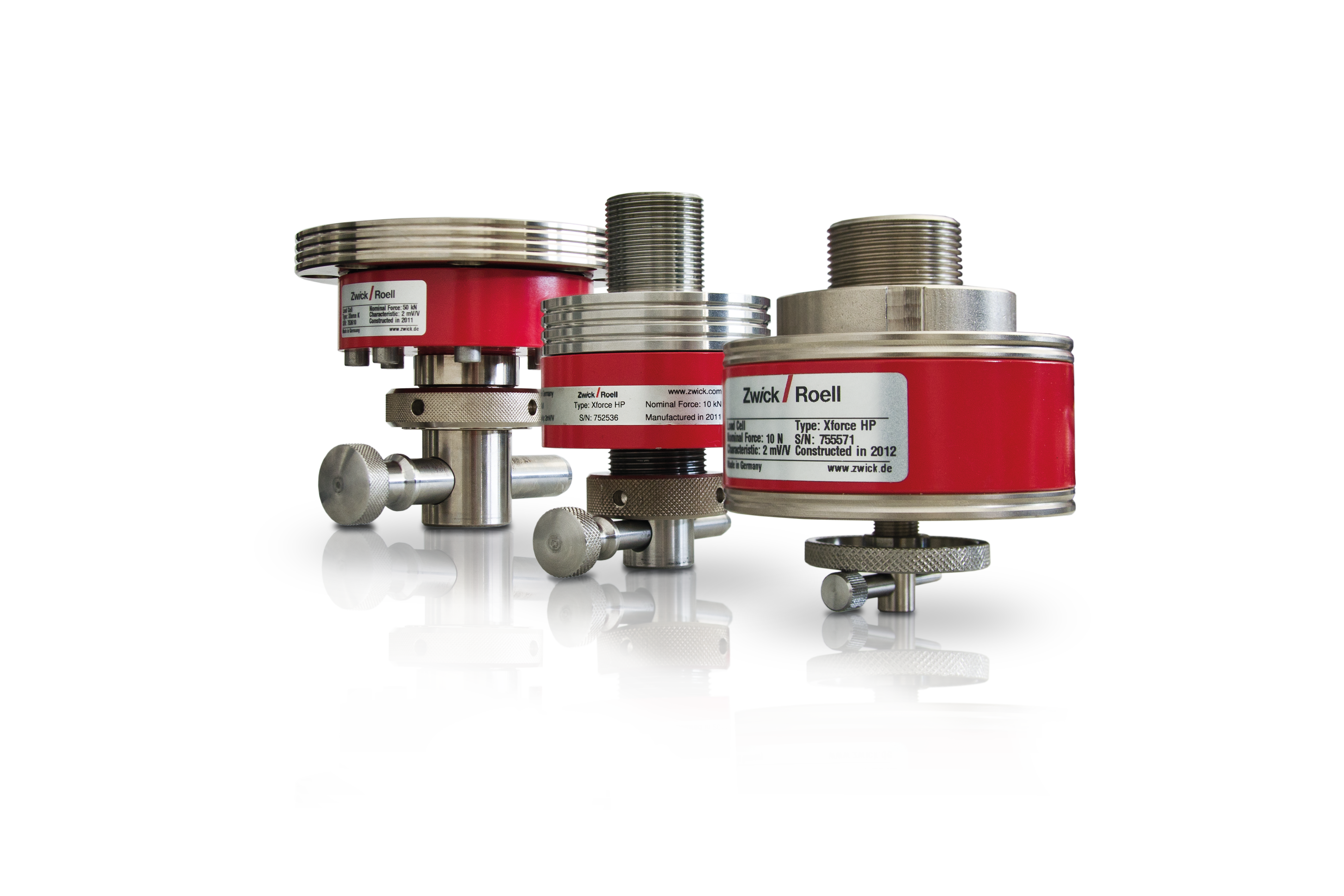
  • 5 N - 2,500 kN (quasi-static)
  • 1 kN - 1,000kN (dynamic)
Accuracy class
  • ISO 7500-1
  • ASTM E4

Load cell comparisons Requirements Advantages & features Accuracy features Optional accessories

In the field of materials testing, a load cell is used to characterize the mechanical properties of a material by measuring the force required to deform or break the material. Load cell sensors convert the physical quantity force into an electrical voltage which can then be measured. Load cells can be used for tensile, compression and flexure tests, as well as torsion and cyclic tests.

Due to the often extreme and diverse requirements in materials testing, the load cell is the heart of the testing system. By nature it provides the prerequisite for reliable, interpretable test results. To ensure that this core component is optimally integrated into the testing system, ZwickRoell has developed and manufactured our own patented Xforce load cell series, which meet the highest requirements in terms of accuracy and robustness.

Load cells in comparison
Xforce Precision P High-precision HP High-precision HP+ 1 K K+ 1 High-capacity Dynamic 2
Nominal force
Fnom
5 N to 150 kN 5 N to 10 kN 5 N to 10 kN 10 kN to 250 kN 10 kN to 250 kN 330 kN to 2,500 kN 1 kN to 1,000 kN
Accuracy Class 1 from x % of Fnom 0.4% 0.2% 0.1% 0.2% 0.1% From 0.2% of Fnom From 0.4% of Fnom
Accuracy class 0.5 2% 1% 0.1% 1% 0.1% From 1% of Fnom From 1% of Fnom
Applications Quasi-static Quasi-static Quasi-static Quasi-static Quasi-static Quasi-static Quasi-static and fatigue tests


1 The plus load cells feature a wider measurement range in which the calibration is valid.
2 The Xforce dynamic load cell is equipped with an integrated accelerometer (from 5 kN).

Load cell requirements

Load cell requirements

Axial force limits
Transverse forces
Temperature
Bending moments
Torque

Axial force limits

Axial force limits and force limits and ranges in the direction of the load cell’s measurement axis. Excessive force in the direction of the measurement axis of the load cell can lead to limited measurement accuracy and permanent deformation of the load cell.

The Xforce load cell can withstand 300% of the nominal force without mechanical failure and up to 150% without zero offset. With the unique electronic identification system within the load cell, our testXpert testing software automatically identifies the load cell and its properties and sets the appropriate force and displacement limits for the test.

Transverse forces

Transverse forces are external forces acting on the mounting surface of the strain gauge perpendicular to the test axis. These forces can negatively influence the test results.

Our Xforce load cells (HP and K) are designed and built for tests that are subject to transverse forces. A transverse force equal to 10 % of the nominal force causes a deviation of only ±0.02 % of the measured value.

Temperature

Temperature fluctuations on the load cell can lead to deformation and influence the test result.

Our Xforce load cells HP and K, in particular, feature an integrated temperature compensation function.

Bending moments

Bending moments occur when a transverse force occurs in an offset manner due to a lever or when the axial force is applied in an offset manner due to an eccentricity.

Xforce load cells are designed to reduce bending moments to a minimum. The deformation elements exhibit high bending stiffness under superimposed transverse forces, bending moments or torques.

Torque

If a transverse force does not impact the measurement axis directly, a torque is generated. Torques are generated by the test arrangement or specimen, e.g., in compression testing of coil springs.

For Xforce load cells, the torque corresponds to 0.2% (P and HP) or 0.005% (K) of the nominal force per mm for each mm of parallel offset.

Video: Xforce load cell

Robust and highly accurate. Don’t just take our word for eat. See for yourself!

Advantages and features of the Xforce load cell

Advantages and features of the Xforce load cell

Unique self-identification feature
Standard-compliant factory calibration
Outstanding linearity
Large measurement range with a load cell
Robust and reliable
Simple, fast and precise assembly of the specimen grips
Fast load cell change

Unique self-identification feature


Save time, prevent errors and rest assured that your load cell is protected.

  • After it is connected, the type and properties of the load cell, including force and travel limits, are automatically imported and identified by our testXpert testing software.
  • The need to manually enter this information is eliminated, preventing possible user input errors.
  • Critical information such as sensor overload conditions and date of occurrence are recorded in the memory of the identification system.

Standard-compliant factory calibration


Rely on the accuracy of your load cell!

  • Certified factory calibration according to ASTM E4 and ISO 7500
  • Before dispatch, each load cell is calibrated with the complete testing system, including the drive and the measurement and control electronics.
  • The calibration information is documented in a factory calibration certificate, which is included with the delivery of the load cell.
More on ISO 7500-1 / ASTM E4

Outstanding linearity


Maximize the value of your test results!

Linearity, or non-linearity indicates the load cell errors over the entire operating range.

ASTM E4 specifies that the relative display deviation cannot be more than 1% of the measured value (typically from 1% to 100% of the nominal force of the load cell):

  • Load cells Xforce HP and Xforce K: the maximum display deviation is 1% of the measured value from 0.1% of the nominal force, and 0.25% of the measured value from 0.4% of the nominal force
  • Load cell Xforce Dynamic: the maximum display deviation is 1% of the measured value from 0.5% of the nominal force, and 0.5% of the measured value from 1% of the nominal force

ISO 7500-1 defines accuracy classes from 0.5 to 3, with the most common calibration of materials testing machines corresponding to class 1:

  • Xforce load cells meet all five criteria of ISO 7500-1, accuracy class 1 and accuracy class 0.5.

Large measurement range with a load cell


The need to purchase and calibrate several load cells is usually unnecessary!

  • Cover several application requirements with a single load cell that features a measuring range of 0.1% up to 100% of the nominal force of the load cell.
  • The available measuring range is not affected by attached test fixture or specimen grip weights up to 45% of the nominal force.

Robust and reliable


Test with confidence!

  • Integrated overload protection
  • The testXpert testing software allows you to set force limits that cause the testing system to shut off automatically.
  • Software and hardware limit switches limit the travel range of the crosshead, protecting your load cells and test tools.
  • Xforce load cells can withstand loads up to 300% of the nominal force without break and up to 150% of the nominal force without zero offset. Therefore overload protection features such as preloaded spring assemblies, mechanical stops or guides for lateral force absorption are usually not necessary.
Work in two test areas with one load cell with mounting studs

Simple, fast and precise assembly of the specimen grips


Easy changes and alignment of test fixtures

  • Each load cell is equipped with a precision-fit mounting stud so that the specimen grips and test tools can be inserted quickly, without play and optimally aligned with the test axis.
  • Reference positions (e.g., test fixture distance) are only set up once and stored in the testXpert testing software.
  • The Xforce K load cell has an optional mounting stud, which allows it to be used in two test areas.
  • Xforce dynamic load cells always have flange connections to ensure dynamic fatigue strength.

Fast load cell change


Time savings through the use of multiple load cells on the same machine

When multiple load cells are used or in case of frequent load cell changes, we recommend the “connection via mounting stud” option. With the mounting stud, you can connect a second load cell to the existing load cell in the testing system, in the same way that a fixture would be attached to the existing load cell. Instead of screwing the load cell on or off every time it needs to be changed, the original load cell remains in place and the mounting stud is added to it. This option provides the following advantages:

  • The cables are not unnecessarily stressed by being screwed on and off
  • Increased flexibility and time savings
  • Immediate alignment with the test axis

How does a load cell work?

The most common industrial load cell is the strain gauge. It works by means of a mechanical deformation element to which strain gauges are attached in the form of a measurement bridge.

When a force is applied to the load cell, the mechanical element to which the strain gauge is attached is elastically deformed. Deformation in the form of mechanical elongation and compression causes the strain gauge to be elongated or compressed. This strain-related (and therefore force-dependent) change in resistance is converted into a measurement signal by the measuring electronics and processed.

A compression load cell measures compression forces and is normally installed below the test fixture. A tension load cell measures tensile forces.

Load cell accuracy

The accuracy of a load cell is determined by applying a measuring error. The smaller the measuring error, the more accurate the load cell. The most common accuracy specification is linearity (or nonlinearity).

Linearity (or non-linearity)
Hysteresis
Repeatability
Temperature variation span and zero point
Graphical representation of the linearity of a load cell

Linearity (or non-linearity)

1 Performance 2 Load 3 Zero adjustment 4 Power rating 5 Non-linearity 6 Hysteresis

Linearity is a mathematical relationship represented by a straight line. In the case of a load cell, it is the relationship between the applied force and the sensor result. The accuracy of a load cell is normally indicated in the form of ±x% of the displayed value.

Example: A 1000 N Xforce HP+ is calibrated in Class 0.5. The accuracy is ±0.5% of the displayed value of the load cell from 1 N to 1000 N. 1 N can be measured with an accuracy of ± 0.005N.

Hysteresis

Hysteresis is defined as the maximum difference between two load cell readings for the same applied load, where one reading is obtained by increasing the load from zero and the other is obtained by decreasing the load from the maximum nominal load of the load cell.

Repeatability

The maximum difference between the load cell readings in repeated load applications under the same loading and environmental conditions.

Temperature variation span and zero point

The change in power or zero point due to a change in the temperature of the load cell.

Learn more about how our load cells can help you solve your testing challenges.

Contact our experts - we look forward to answering any questions you may have.

Contact us

Optional load cell accessories

Daily Check device

The Daily Check device is used for regular checks on load cells up to 500 N by means of comparison values which have been measured following recalibration/adjustment. The device consists of two reference standards (master/slave).

  • Implementation of the fixtures and software on any number of machines through simple installation and removal.
  • Detection of systematic errors in compression and tensile direction in the load cell.
  • Reliable test results: Performing checks between periodic calibrations ensures that the load cell transducer is free of systematic errors.
  • The results of the daily check are documented in a testXpert report.
  • Traceability: All safety-critical tests have specific requirements in terms of traceability and documentation. With our ZwickRoell testing software, the administrator can specify what is to be recorded and for which operations and events justifications must be added.

Xforce load measuring system with load bypass unit

Load cells with load bypass unit are particularly suitable when:

  • Tests are performed at high test speed, since here there is a possible risk that the set force limits don’t react quickly enough.
  • Tests take place with small separation between test tools or with short travel distances; therefore, also particularly well suited for spring and component testing.

For tests in the compression direction, Xforce HP load cells are protected by mechanical overload protection and an integrated load bypass unit.

  • In case of mechanical overload protection, a mechanical stop blocks it before reaching the maximum permissible limit force of the load cell. This prevents any damage to the load cell due to overloading.
  • The integrated load bypass unit protects the entire test arrangement: Starting at force threshold 120+6/-4% Fnom, the existing force is transferred to several springs. As a result, the entire test arrangement bypasses a load. This load bypass prevents a force increase in the load cell that would cause overloading or even destruction.

Examples of testing machines that use load cells

Downloads for load cells

Name Type Size Download
  • Product Information: Xforce K Load Cell PDF 3 MB
  • Product Information: Xforce HP Load Cell PDF 383 KB
  • Product Information: Xforce HP+ and Xforce K+ Load Cells PDF 3 MB
  • Product Information: Load Cells 330 kN - 2,500 kN PDF 244 KB
  • Product Information: Xforce Load Cell, Dynamics PDF 314 KB
  • Product Information: Xforce Load Measuring System with Load Bypass Unit PDF 389 KB
  • Daily Check PDF 750 KB

Frequently asked questions

The load cell sensor works by means of a mechanical deformation element to which strain gauges are attached in the form of a measurement bridge. When a force is applied to the load cell, the mechanical element to which the strain gauge is attached is elastically deformed. Deformation in the form of mechanical elongation and compression causes the strain gauge to be elongated or compressed. This strain-related (and therefore force-proportional) change in resistance is converted into a measurement signal by the measuring electronics and processed.

A load cell converts forces caused by tension, compression or torsion into an electrical signal that can be measured, read and recorded.

The main component of a load cell is a mechanical deformation element to which strain gauges are attached.

A strain gauge is a sensor that measures deformation caused by a change in electrical resistance. In materials testing, strain gauges are used in load cells.

A load cell is used to measure the force acting on the sensor. They are used to determine compression forces or tensile forces, but are also suitable for dynamic test tasks.

Top