Thermomechanical Fatigue - ASTM E2368 and ISO 12111
For the design and construction of thermal and simultaneously mechanical cyclically loaded components for gas turbines or combustion engines for example, reliable characteristic values for the prediction of the fatigue life and the cyclic deformation behavior under existing operating conditions must be available. For the determination of thermomechanical fatigue (TMF), the required material characteristics are determined through the in-phase or out-of-phase combination of cyclic thermal and mechanical loads.
TMF testing is described in the following specific standards: ASTM E2368, ISO 12111 and the Validated Code-of-Practice for Strain-Controlled Thermo-Mechanical Fatigue Testing.
Objective & application Standards Running a test Testing system VIDEO Download Request a consultation

What is thermomechanical fatigue?
Aside from reliability during long-term operation, the power plant and aircraft turbines must show sufficient resistance against short-term load changes and start-stop processes. Thermomechanical fatigue (TMF) is the simulation of this mechanical load as a result of the thermal expansion of the material. During startup, the temperature of all components rises from room temperature to operating temperature, which is accompanied by an expansion of the material. This expansion creates a stress in the material, which must be determined with accuracy to prevent component damage. For composite components such as turbine blades with ceramic thermal barrier coatings, the thermal mismatch between metallic and ceramic components leads to another loading component that must be considered during design. Also, adhesive oxide coatings influence the fatigue life during operation.
Relevant standards for thermomechanical fatigue
TMF testing requirements are described in more detail in the following standards:
- ASTM E2368 Standard Practice for Strain Controlled Thermomechanical Fatigue Testing
- ISO 12111 Metallic materials - Fatigue testing - Strain-controlled thermomechanical fatigue testing method
- Validated Code-of-Practice for Strain-Controlled Thermo-Mechanical Fatigue Testing
Performing the TMF test according to ASTM E2368 and ISO 12111
When determining thermomechanical fatigue according to ASTM E2368 and ISO 12111, a specimen is cyclically heated while being simultaneously loaded with mechanical in-phase or out-of-phase (anti-phase) strain. Depending on the damage mechanisms to be tested, different temperature and mechanical strain sequences can be parameterized. Curves are often triangular and hold periods can be added at peak temperature, for example. Furthermore, temperature and strain can be applied in-phase and out-of-phase. This phase shift between cyclic thermal and mechanical loading significantly affects the fatigue life as well as the plastic deformation of the material.
The most common TMF tests (with and without phase shift) are:
- IP (in-phase): the specimen simultaneously undergoes thermal strain through heating and mechanical strain due to tensile force
- OP (out-of-phase): the specimen simultaneously undergoes thermal strain through heating and compression due to compressive force
- CD (clockwise diamond)
- CCD (counterclockwise diamond)
TMF tests are mainly strain-controlled, since the load acting on the component is caused by obstruction of the thermal strain. Stress-controlled tests are sometimes associated with non-uniform specimens, e.g. with notches, since here the strain in the notch base cannot be measured. In both cases, only the total strain (εt) can be measured and controlled. It is composed of thermal strain (εth) and mechanical strain (εme): formula εt = εth + εme. In order to load the specimen with the desired mechanical strain in addition to the thermal strain, the thermal strain with the defined temperature phase is measured in advance in a time-based manner and taken into account in the control of total strain during the actual test.

Determination of the Young’s modulus before every TMF test
The Validated Code-of-Practice for Strain-Controlled Thermo-Mechanical Fatigue Testing recommends the determination of the Young’s modulus at ambient temperature, minimum temperature, maximum temperature and at least one additional mean temperature value before every TMF test. Both the ASTM E2368 and ISO 12111 standards also require measurement of the Young's modulus at minimum, mean and maximum temperature of the thermal cycle.
A subsequent comparison of the measured Young’s modulus value with data from a reference database serves as verification of the correct control and measurement values of force, strain and temperature. If the measured values are within the tolerance limit of max. 5% of the expected stress range at minimum and maximum force, you can be assured that test operation is correct.
Strain measurement to ASTM E2368 and ISO 12111
ASTM E2368 requires the use of an extensometer that at a minimum meets accuracy class B-2 to ASTM E83. ISO 12111 and the Validated Code-of-Practice specify and extensometer meeting accuracy class 1 or better according to ISO 9513. For specimens with a gauge length less than 15 mm, the extensometer must correspond with accuracy class 0.5 according to ISO 9513.
Further strain measurement requirements for thermomechanical fatigue testing:
- The extensometer must be suitable for dynamic strain measurement over an extended period of time, while ensuring minimum drift, slip and hysteresis.
- The extensometer must be protected from thermal fluctuations or influences by using an active cooling system, such as a water cooler.
- The contact pressure of the extensometer on the specimen should be kept as low as possible, without damaging the specimen surface.
- The extensometer must be mounted in such a way that when the specimen heats up and expands, the strain measurement is not impaired and the sensor arms are prevented from slipping off the specimen.
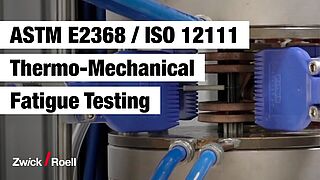
Testing system for determination of thermomechanical fatigue
For thermomechanical fatigue testing, ZwickRoell in Fürstenfeld developed a new electromechanical testing system in close collaboration with the Karlsruhe Institute of Technology (KIT) . The Kappa 100 SS-CF was equipped with an induction heating system for a temperature range of 50 °C up to 1,200 °C and an air cooling system. This electromechanical creep testing machine with backlash-free zero crossing has proven itself for tests with low-frequency load cycles for many years. The Kappa SS-CF controls zero backlash under cyclic tensile and compression loads, as specified in ASTM E2368 and ISO 12111.
The testing machine is equipped with water-cooled hydraulic grips for secure hold of the specimen. Water cooling enables fast temperature stabilization along the specimen and ensures direct heat outflow from the specimen end. Reliability of the strain measurement during the TMF test is ensured through a contacting extensometer with ceramic sensor arms and water cooling.
This testing system for the determination of thermomechanical fatigue meets all the requirements of the commonly used ASTM E2368 and ISO 12111 standards as well as the Validated Code-of-Practice for Strain-Controlled Thermo-Mechanical Fatigue Testing.
The components used for the TMF test can also be installed in servohydraulic testing machines.


Optimal temperature distribution for TMF testing
According to the Validated Code-of-Practice for Strain-Controlled Thermo-Mechanical Fatigue Testing the temperature deviation of the specified set value in the measured specimen section is < 10K or < ±2% of the temperature difference. Depending on the specimen shape and material, heating and cooling rates of up to 25K can be used. To reach the maximum heating and cooling rates specified in the standards, we rely on an induction heating system and specially arranged cooling jets when performing TMF tests.
The induction heating system with individually adjustable heating power allows you to test different specimen materials with varying electrical conductivity. Specimen-related inductors ensure optimal temperature distribution on the specimen. Proportional pressure control valves and four symmetrically arranged flat spray nozzles ensure precise air flow control. The cooling nozzles are adjustable and the position is reproducible for future tests.
The temperature is controlled according to ASTM E2368 and ISO 12111 via ribbon thermocouples directly on the specimen. These are easily and reliably attached in the center of the measured specimen section. Adjustable spring pre-tensioning ensures reliable contact pressure.