ISO 527-1 & ISO 527-2 Tensile Test on Plastics
This tensile test is used to determine essential mechanical properties of molding materials. These characteristic values are mostly used for comparison purposes. The standards ISO 527-1 (general principles) and ISO 527-2 (test conditions for molding and extrusion materials) describe tensile testing on plastics with a thickness of more than 1 mm. The guiding principle of the ISO 527 standard is the high reproducibility of test results across laboratories, companies and national borders.
More details about the tensile test on plastics can be found in the ASTM D638 standard. Plastic films and sheets with a thickness of less than 1 mm are described in the ISO 527-3 or ASTM D882 standards.
Objective and characteristic values Running the test Specimen shapes & dimensions Environmental conditions Accuracy requirements Comparison to other test methods Testing systems Downloads


Objective and characteristic values of the tensile test to ISO 527
A series of characteristic values are determined to describe the essential mechanical properties of a molding material. These characteristic values are mostly used for comparison purposes.
Typical characteristic values are:
- Tensile stress: force related to the initial cross section of the specimen
- Strain: change in gauge length with reference to the initial gauge-length
- Tensile modulus: gradient of the curve in the stress-strain diagram
- Yield point: stress and strain at the curve plot point at which the gradient is zero
- Point of break: stress and strain at the moment of specimen break
- Poisson's ratio: negative ratio of transverse strain to axial strain
Both ISO 527-1/-2 and ASTM D638 define test methods for tensile tests. The two standards are technically equivalent but do not provide fully comparable results, because specimen shapes, test speeds and the method of result determination differ in some respects.
In the standardized tensile test, results are based on a defined specimen pull-off speed on the specimen. However, the loads on a component or structure in actual service may lie within a very wide range of the deformation rate. Due to the viscoelastic properties of polymers, mechanical properties different from those measured on a standardized test specimen normally result under altered strain rates. For this reason the characteristic values determined in a tensile test are only of limited suitability for component design, but represent a very reliable basis for material comparisons.
Aging tests
The tensile test provides a good basis for demonstrating the change in the mechanical characteristic values of a polymer following aging, heat or medium aging, or weathering. Here, the characteristic values of the tensile test are determined in the newly molded state, as well as after defined aging or weathering periods.

How is the ISO 527-1 tensile test performed?
Both ISO 527-1/-2 and ASTM D638 define test methods for tensile tests. The two standards are technically equivalent but do not provide fully comparable results, because specimen shapes, test speeds and the method of result determination differ in some respects.
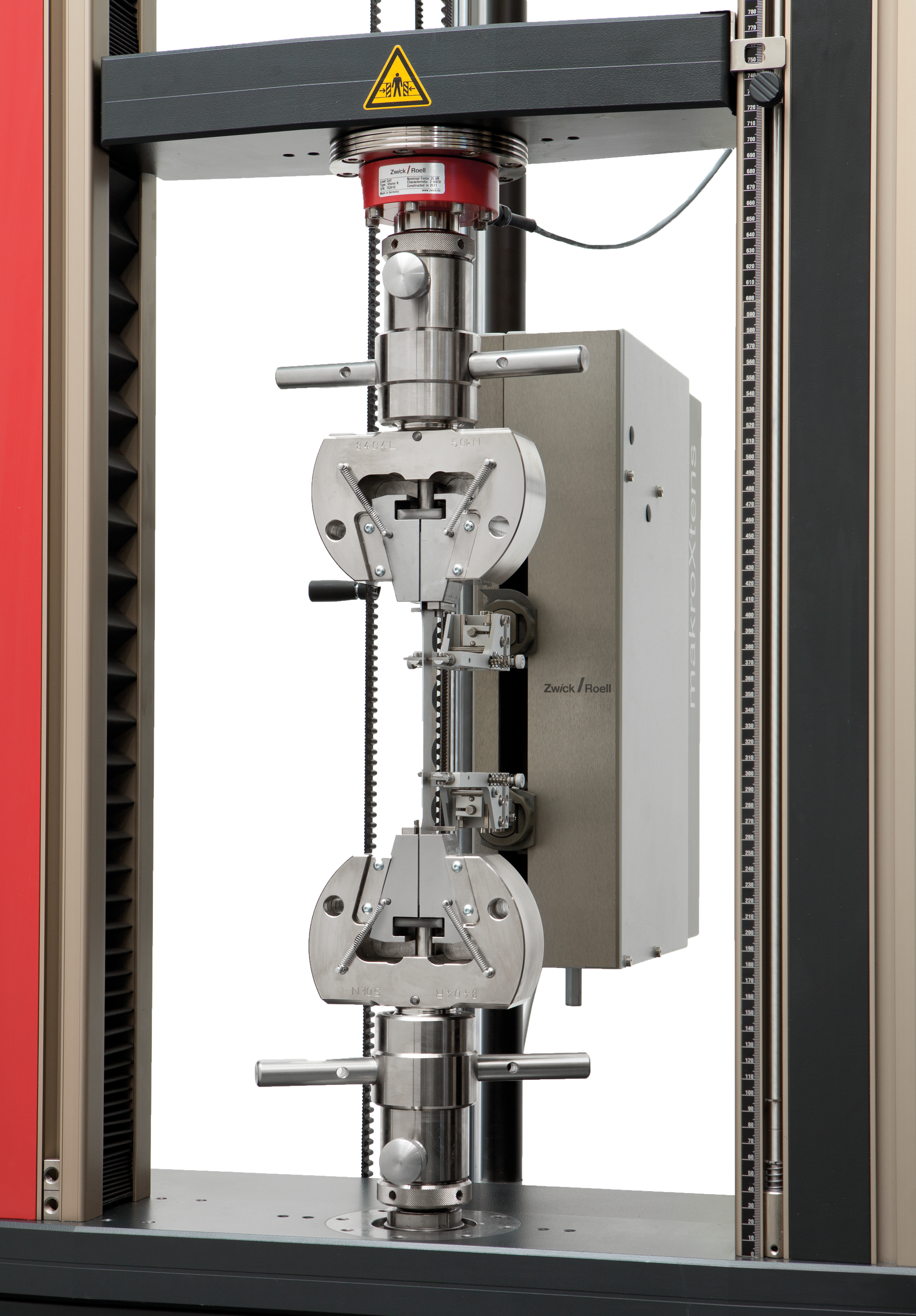
Performing the tensile test to ISO 527:
ISO 527-1/-2 first defines the specimen shapes, the accuracy for the specimen dimension measurement, the permitted tolerances and the initial gauge length. After setting the specified tool separation distance, the specimen is gripped. A specified pre-load ensures reproducible results, independent from the operator. Different typical characteristic values are determined using the tensile test in accordance with ISO 527. Here, determination of the tensile modulus places significantly higher requirements on the measurement accuracy, which are defined in Annex C of ISO 527-1. The exact requirements on the environment and test equipment used for the ISO 527 tensile tests can be found below.
The easiest way to perform the test is using the testXpert standard test program for the ISO 527-1/-2 standard. All settings for performing tests to ISO 527 have already been preset with guaranteed standard compliance.


Start testing to ISO 527 immediately with testXpert
Efficient testing to ISO 527 and fast onboarding of new employees is ensured in the following way:
- Eliminate the need to study the standard: guaranteed standard compliance through the standard test program for ISO 527-1/-2, where all characteristic values and parameters for ISO 527-1/-2 have already been saved.
- Due to the user management feature, users only see the information they need to run the test, which means that they can be quickly trained and reliably perform the tests according to ISO 527. Nothing is forgotten.
- Maximum testing efficiency is achieved through the connection of peripheral devices: When the specimen dimensions from the micrometer are sent directly to the testing software, you save time and avoid input errors.
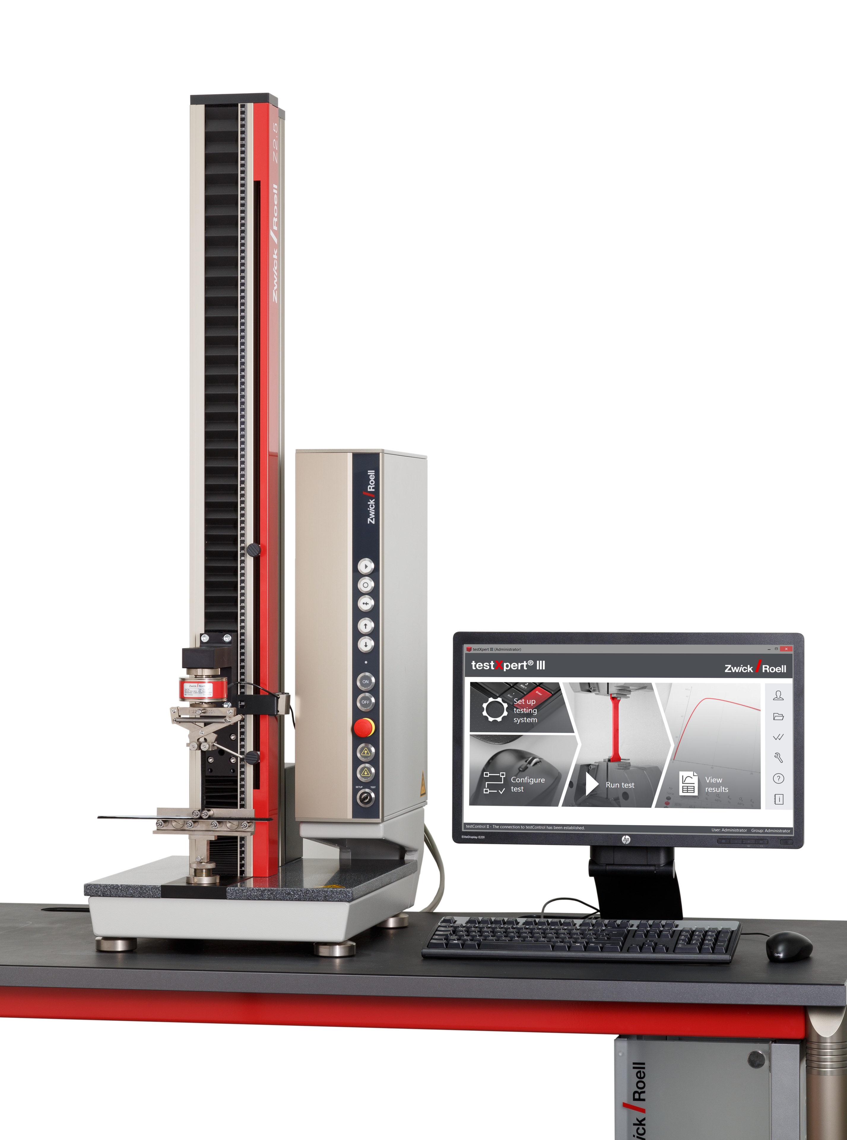
testXpert testing software Running the test in 6 steps with testXpert
Specimen types / specimen shapes
The overriding goal of testing molding materials is to achieve a high degree of reproducibility. This requires you to limit the number of specimen types. The shape and dimensions of the specimens are defined in ISO 527-2. The preferred specimens are type 1A (injection molded) and type 1B (pressed or mechanically machined):
Specimen type 1A to ISO 527-2
- The specimens are usually produced by injection molding. Type 1A specimens as defined in ISO 527-2 are used; in ISO 3167 these are designated as type A specimens and are additionally restricted to a specified thickness of 4mm. This specimen is also included in ISO 20753 as specimen A1.
- Injection molded specimens display decreasing orientation as the distance from the feed point increases, leading to non-constant mechanical property curves along the length of the specimen, and therefore frequently resulting in specimen break on the side away from the gate.
- The preferred gauge length for the specimen is 75mm, or alternatively 50mm.
Specimen type 1B
- As an alternative, type 1B specimens can be used; these are designated as type B in ISO 3167 and as type A2 in ISO 20753.
- They are generally machined from pressed or injection molded sheets. The orientations of the polymer normally differ significantly from those in injection molded specimens. Comparability of results obtained using different specimen shapes is not guaranteed.
- A gauge length of 50 mm is specified for type 1B specimens due to the larger radius and therefore shorter parallel area.


| Standard | Specimen type | Note | l3 mm | l1 mm | b2 mm | b1 mm | h mm | L0 mm | L mm |
|---|---|---|---|---|---|---|---|---|---|
| ISO 527-2 | 1A | Injection molded specimen (preferred form) | =170 | 80±2 | 20±0.2 | 10±0.2 | 4.0±0.2 (preferred) | 75±0.5 or 50±0.5 | 115±1 |
| ISO 527-2 | 1B | Pressed specimen or mech. machined (preferred form) | ≥150 | 60±0.5 | 20±0.2 | 10±0.2 | 4.0±0.2 (preferred) | 50±0.5 | 115±1 |
Specimens for aging tests, media aging tests, and weathering tests
- A small cross-section is advantageous for all aging procedures which progress from the surface of the specimen.
- Often only the maximum tensile stress is used for assessment of this behavior. The use of extensometers is not necessary, and thin, waisted specimens can be used.
- ISO 527 offers Types CP and CW for this purpose; these are borrowed from impact tensile standard ISO 8256.

Specimen dimensions
- Determining the specimen dimensions can result in a relatively high number of stress value errors. When a specimen is subjected to a tensile load, the measurement error is reflected linearly by the stress result. When a specimen is subjected to a flexure load, the specimen thickness measurement error has a quadratic effect.
- In addition to the reading accuracy of the measuring equipment, the size and form of the contact element and the applied surface pressing during measurement also play an important role.
- Furthermore, the cross-section of the specimen often differs from an ideal rectangular form. This could be angular errors resulting from mechanical processing or sink marks and minor draft angles in injection molded specimens.
- Many test standards refer to ISO 16012 and/or ASTM D5947 for defining the requirements and methods of dimensional measurements. Sometimes, individual test standards contain additional specifications.
- For example, a caliper is normally used to measure the overall length of hard plastics larger than 10 mm. Since surface pressing during measurement cannot be checked, measurement accuracy is rather low even if the resolution of the caliper is high.
- The thickness and width of the specimen is normally determined by a micrometer screw with ratchet. The contact surface is flat and circular with a diameter of 6.35 mm. The ratchet limits the measurement force to 5–15 N.
- In automated systems, the thickness and width is determined by a cross-section measuring device. This device holds the specimen during measurement and determines the dimensions with four digital measuring transducers, a defined measurement force, and sensor feet.
- For soft plastics and films, it is imperative that the measurement force is strictly observed. To ensure this, digital thickness measuring instruments with dead weight supports must be used.
Conditioning and environmental conditions
- Observing defined conditioning and ambient conditions with regard to temperature and humidity is of great importance for the comparability of test results.
- Specifications for the conditioning duration can usually be found in the material standards for the plastic being tested. Furthermore, specimens used in tests on molding materials must be kept in a standard atmosphere (standardized temperature and humidity conditions) for at least 16 hours prior to the test.
- A standard atmosphere for testing refers to a defined standard atmosphere as specified in ISO 291 or ASTM D618.
Temperate atmosphere: 23 ± 2 °C, 50 ± 10 %rh
Sub-tropical atmosphere: 27 ± 2 °C, 65 ± 10 %rh - The tolerances correspond to class 2. The tolerances are halved for class 1.
- Room temperature usually refers to a somewhat wider temperature range, between 18 °C and 28 °C.
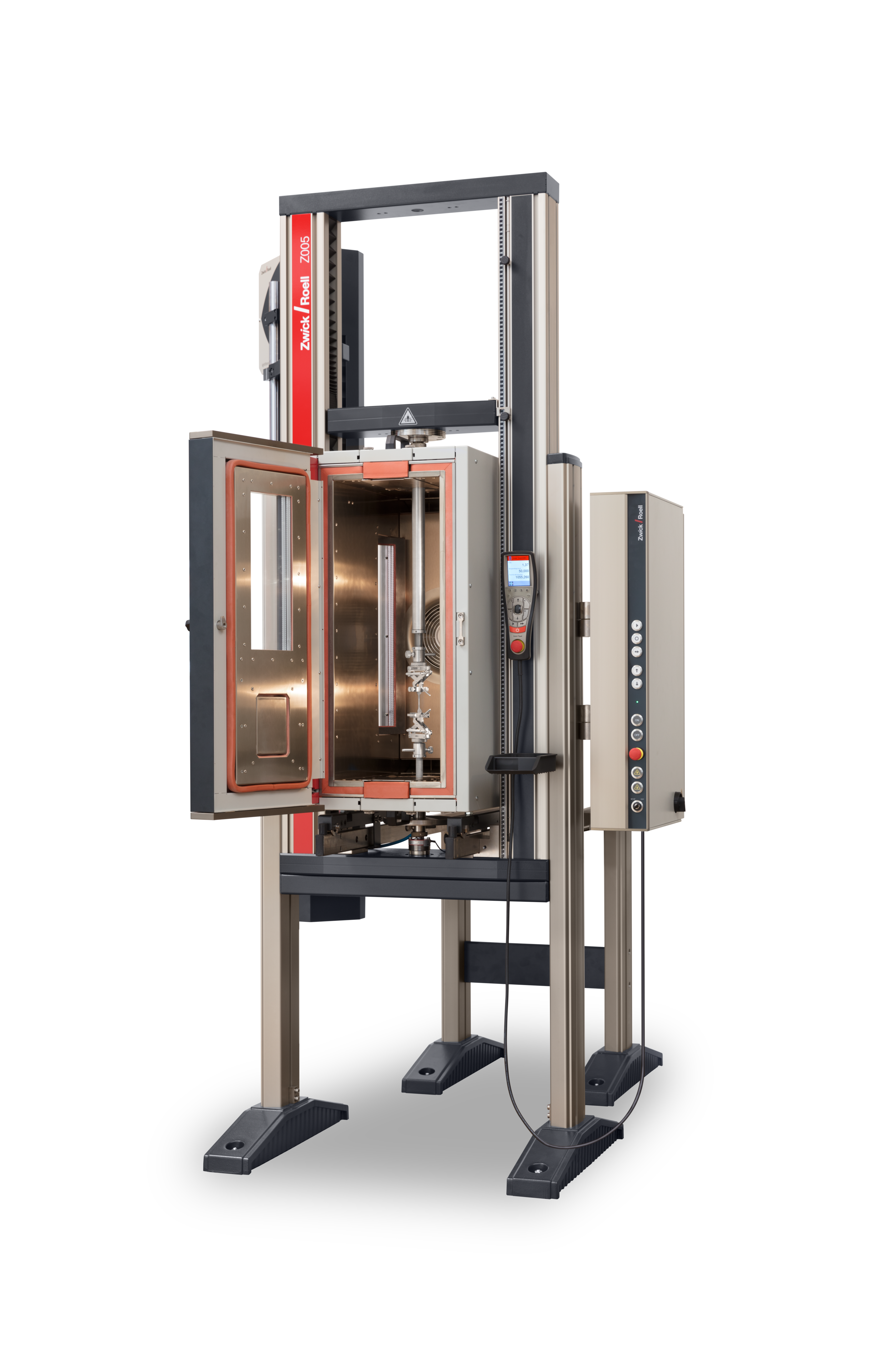
- Tests can also be performed at high or low temperatures, however, different requirements may be specified.
Testing machine accuracy requirements
Testing machines measure two fundamental values: force and extension. Within the framework of a periodic calibration when compared to a measuring instrument traceable to a national standard, evidence has shown that these measured values achieve a level of accuracy defined in the test standard across defined measuring ranges.
Force measurement (ISO 7500-1, ASTM E4)
Most test standards require a measurement accuracy of 1% for the measured value. This requirement is categorized as Class 1 in the ISO environment. Almost all modern testing machines today achieve Class 1 accuracy, or even Class 0.5 with tolerances that are halved. Decisive is therefore the measurement range in which a test machine achieves the specified class accuracy. Various ZwickRoell testing machines achieve Class 1 at a little as 1\1000 of their measurement range. This means you can measure the modulus values and tensile stress of many materials with the same test arrangement and without having to reconfigure the arrangement.
Extension measurement (ISO 9513, ASTM E83)
Along with a defined relative (in percentage) error, the class specifications for measuring extension also include a specification for an absolute error, which occurs when measuring smaller extensions.
ISO and ASTM differ here significantly.
- While ISO tolerances refer to the extension, reference is made directly to strain in ASTM.
- Furthermore, the requirements for smaller strains are defined more narrowly in ISO than in the corresponding ASTM class.
- Depending on the gauge length used, this sometimes results in significant differences by definition, in particular when measuring small extensions.
")
Special considerations for measurement of a tensile modulus
- As seen in the table above, the accuracy requirements for the strain range of the tensile modulus in ISO Class 1 are ±3 µm. This means that a deviation of up to 6 µm may exist between measurements at the beginning and end of the modulus range. This would result in a correspondingly large measurement error.
- To solve this problem, an additional requirement for measuring the tensile modulus was added to ISO 527-1. This additional requirement states that the measurement path between the beginning and end of modulus determination must be measured with an accuracy of 1%.

")
")
")
")