Energy Release Rate (G)
Energy release rates as fracture mechanical characteristic values play a major role in the characterization of composites.
The interlaminate energy release rate G is a parameter used in materials science, particularly in the area of composites, to quantify the crack propagation between the individual layers of a composite laminate. It indicates how much energy is required per unit area to drive a crack between the layers. This is of significant interest as it helps to predict and control crack propagation and thus structural integrity in the development and evaluation of composite materials and structures.
The following test methods are used to determine the interlaminar energy release rate:
- Mode I as double cantilever beam (DCB test) to ASTM D5528 - Crack growth by tensile loading perpendicular to the crack surface/crack opening
- Mode II mostly in ENF test (end notch flexure) to ASTM D7905 - Crack growth by shear loading in the laminate cross section
- Mixed mode bending test (MMB test) - allows the simultaneous investigation of Mode I and Mode II crack growth and thus offers the advantage of simulating more realistic crack propagation conditions in materials and structures, which is more relevant in many practical applications than the isolated consideration of Mode I or Mode II
Standards overview Mode I Mode II Mixed Mode I/II Downloads Request a consultation
")
Standardized method for determining the energy release rate Gc
The test methods defined in the standards for determining the energy release rate provide information about the crack surface-related energy that must be applied to a defined specimen in order to drive a crack. The result is therefore a value that describes the crack propagation sensitivity of a laminate. The measurement is differentiated according to the type of stress:
| Mode I* | Mode II | Mode II | Mixed mode I/II | |
|---|---|---|---|---|
| Test arrangement | Double cantilever beam test (DCB test) | End notch flexure test (ENF test) | Calibrated end loaded split test (C-ELS test) | Mixed mode test (MMB test) |
| Type of load |
|
|
|
|
| Standards |
|
|
|
|
* Mode I is most commonly used
Mode II end notch flexure (ENF) test ASTM D7905, EN 6034
Mode II, in-plane shear, is often measured using the ENF test (end notch flexure).
Mode II loading can generally be applied and measured in a flexure test and in a tensile and compression test with notched specimens.
The measurement of the Mode II energy release rate is standardized in ASTM D7905, EN 6034 as a flexure test, which is carried out as a 3-point flexure test or, less common, as a 4-point flexure test. Here, the shear stresses occurring in the flexure test are used to propagate the crack.
The specimens are denoted with SENB (single end notch bending), but ENF (end notch flexure) is also a term commonly used. Deflection is measured via the crosshead travel (with correction for stiffness) or using a displacement transducer centrally attached.
The crack initiation point is characterized by a maximum force. At the end of measurement, the specimen is cooled in liquid nitrogen and then completely broken to measure the fracture surfaces.


 Mode II 4-point flexure test setup")
Mixed mode bending test (MMB test) ASTM D6671
The mixed mode bending test (MMB test) allows the simultaneous investigation of Mode I and Mode II crack growth and thus offers the advantage of simulating more realistic crack propagation conditions in materials and structures, which is more relevant in many practical applications than the isolated consideration of Mode I or Mode II.
- The mixed mode bending test (MMB test) is described in standard ASTM D6671.
- Mixed mode bending can be measured on unidirectional laminates.
- Crack opening (Mode I) is generated by applying tensile force via hinges. In-plane shear (Mode II) is generated by flexural loading. The crack opening to shear ratio is adjusted by moving the lever arm force application point. It ranges from 100% Mode II loading to a significant Mode I superimposition.


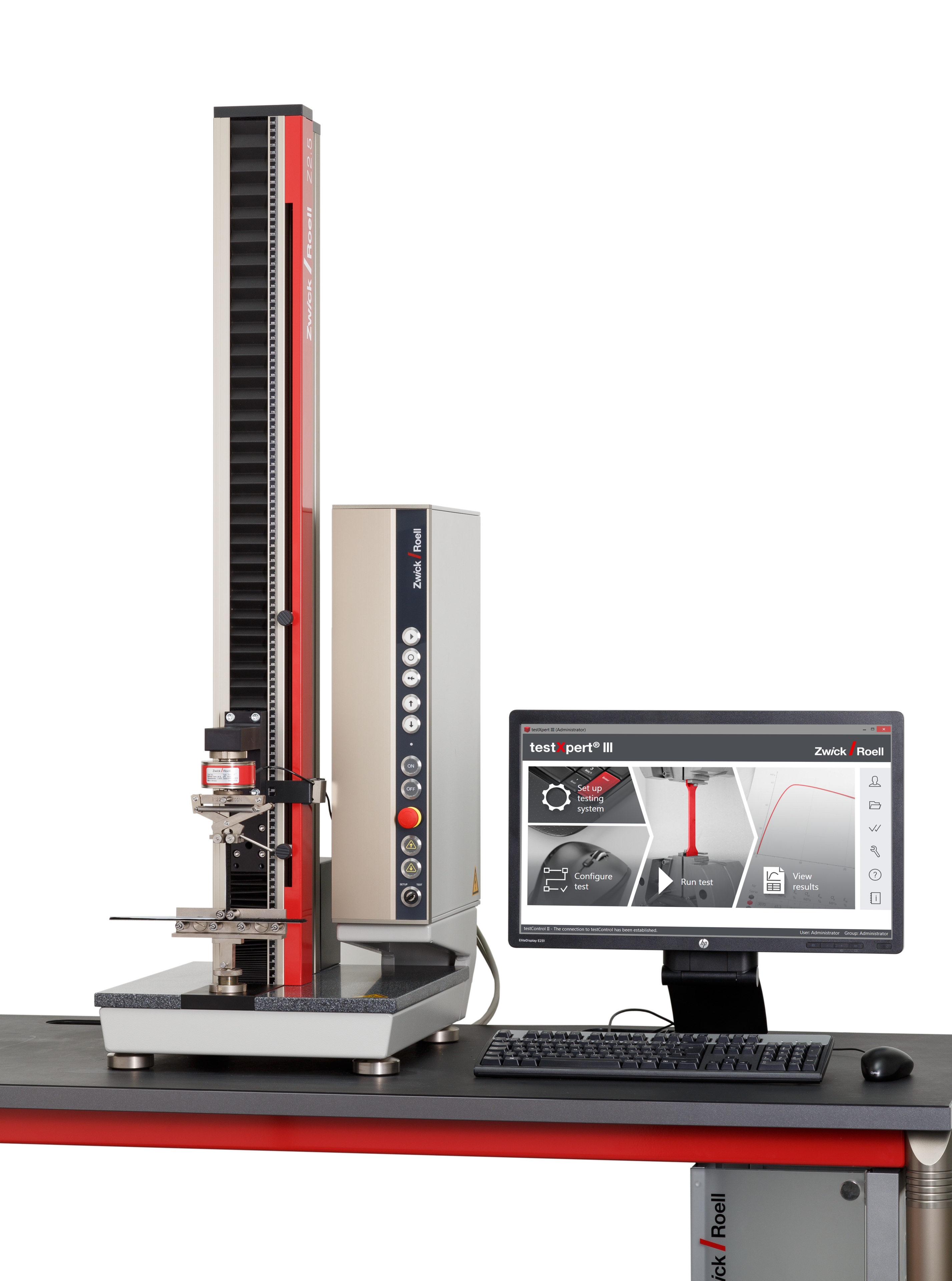


Take advantage of the leading testing software in materials testing
ZwickRoell’s testXpert testing software offers:
- Simple operation: start testing right away and be a testXpert while maintaining maximum safety.
- Reliable and efficient testing: benefit from reliable test results and maximum testing efficiency.
- Flexible integration: testXpert is the optimal solution for all of your applications and processes—simply put, a more effective workflow.
- Future-proof design: testing software for the entire life cycle, ready for your future test tasks!