Testing of Threads, Yarns, and Twine
The physical characteristics of these primary textiles are mainly determined by tensile tests, with specimen preparation as specified by the relevant standard.
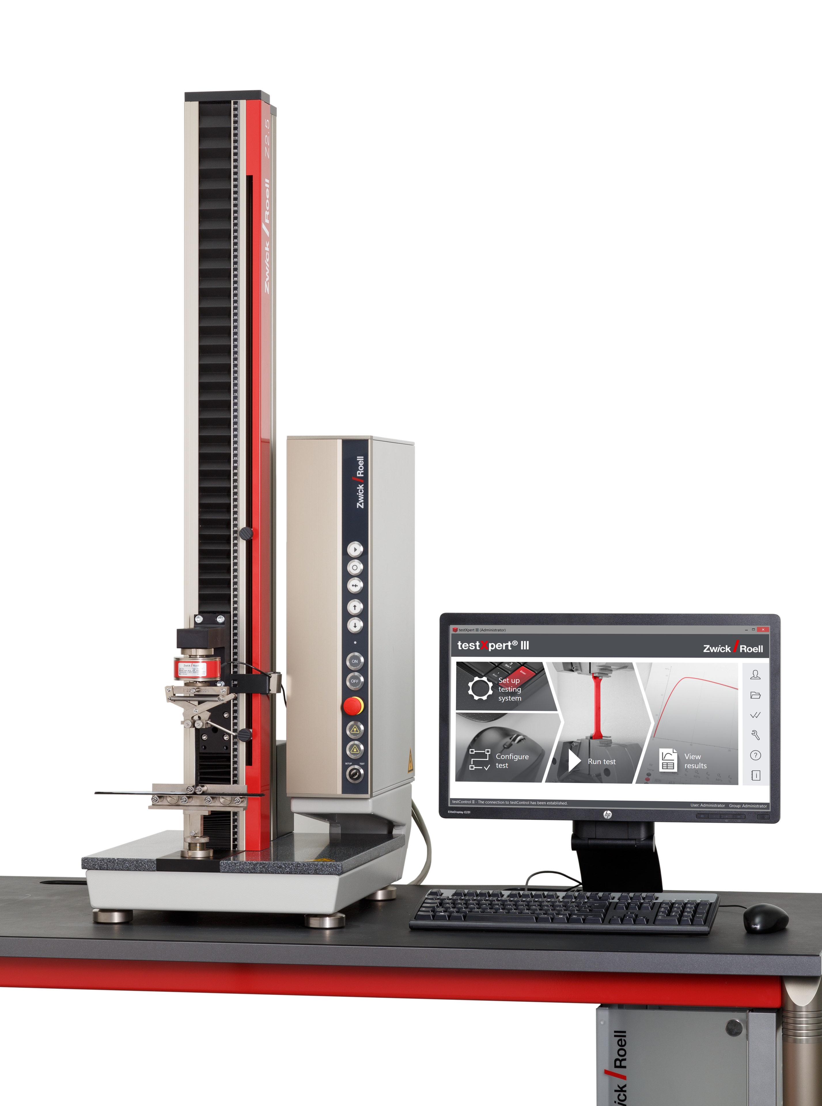
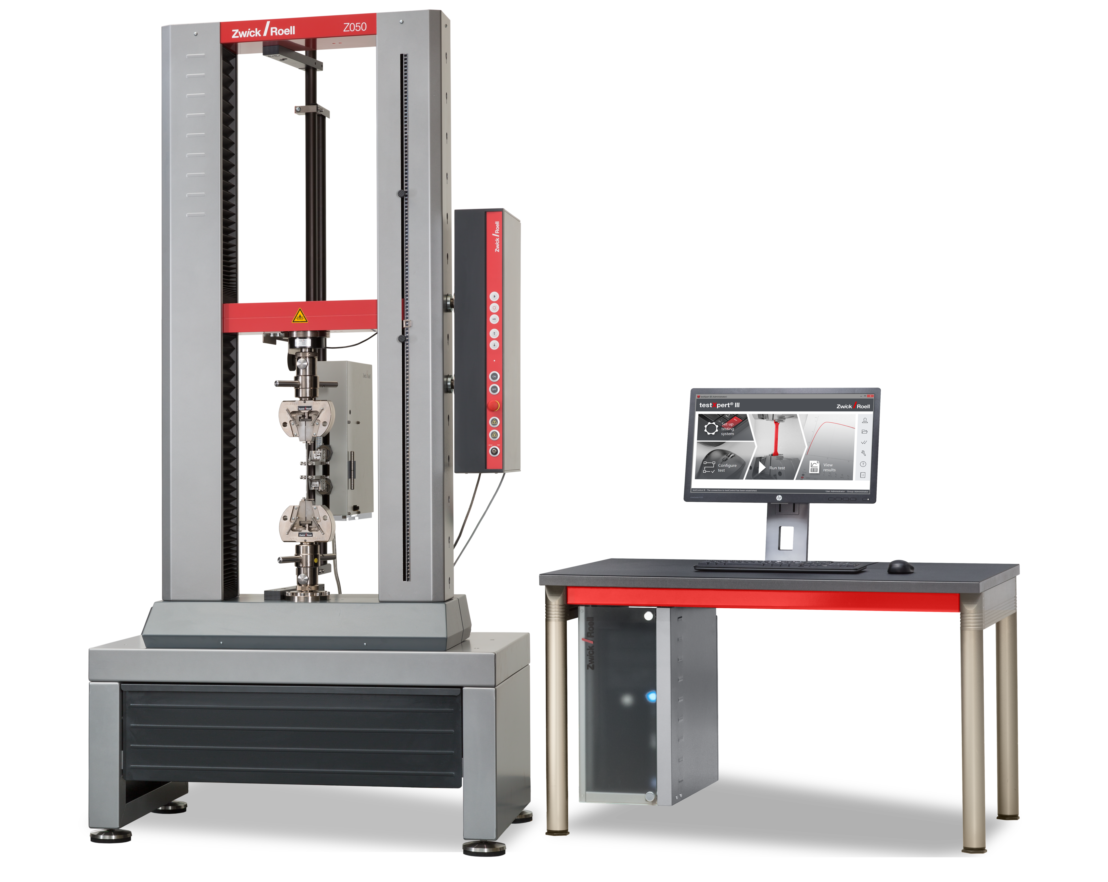
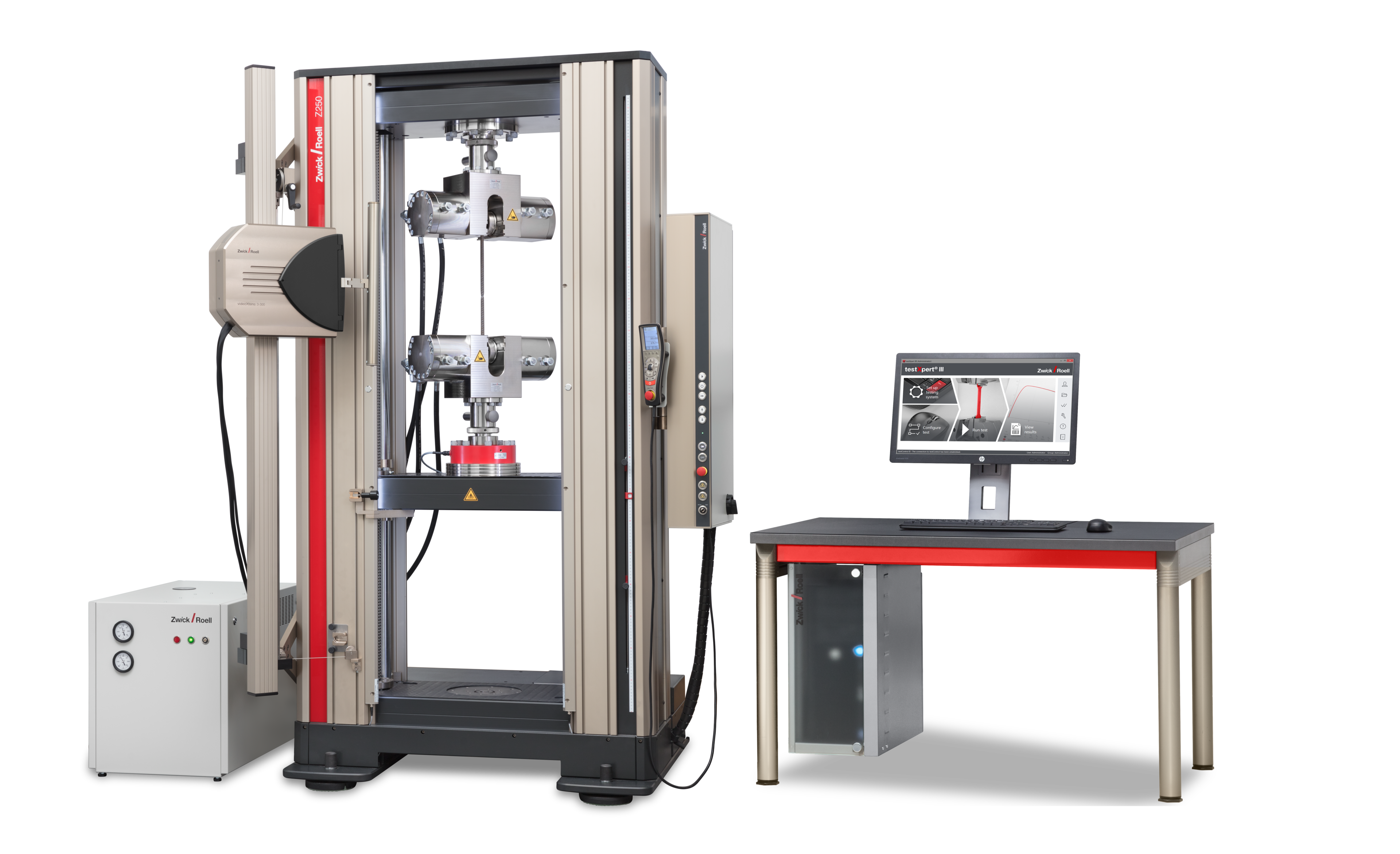
ZwickRoell has suitable testing machines and extensometers, but above all appropriate specimen grips and jaw inserts as well as the proven testXpert testing software, which guarantee a reliable test sequence.

Tensile Tests on Sewing Thread to EN ISO 2062
Tensile tests on sewing thread are carried out according to DIN EN ISO 2062. In this example, screw grips are used and the strain is measured via the crosshead travel, with results shown in a typical force-strain diagram.
The grip-to-grip separation is 250 mm or 500 mm. The test speed is dependent on the grip-to-grip separation. With 250 mm grip-to-grip separation a 250 mm/min is used and with 500 mm grip-to-grip separation the required 500 mm/min. The maximum tensile force and the maximum strain are determined.

Tensile Tests on Aramid Yarn to EN ISO 12562
Tensile tests on aramid yarn are carried out according to DIN EN 12562. Capstan grips are used, with results shown in a typical force-strain diagram.
The force reduction curve enables defined grip-to-grip separation during the test; thus direct extension measurement is not necessary during the test.
The force reduction curve reduces the tensile strength before end clamping. The specimen is held securely preventing jaw breaks, and the test is performed according to the standard. The specimen should break in the free clamping length and not in the deflectors.
An extension measuring system is used for higher measurement accuracy without clamping influence. A mechanical measuring system should be used only when the risk of damage at specimen break does not exist.

Elastic Behavior of Elastic Yarn to DIN 53835-2, -3
According to this standard, the test is used to evaluate the elastic behavior of monofilaments of elastofibers by repeated tensile load between constant offset yields. This standard is applicable to all filament yarns made from elastic yarn that have more than 300% elongation.
Tests on elastic yarns (in this case 0% to 300% elongation with a grip-to-grip separation of 100 mm) are loaded with 5 cycles not until break but between defined offset yields. The specimen is moved 500 mm/min between the point of load application (300% elongation) and the point of load removal. To not distort the results there should be no delay at the reversal points.
The residual force is determined in the 5th cycle and the remaining strain as well as the deformation of the elastic yarn is determined. In this example, spring loaded grips are used to perform the test. The test is shown in a typical force-strain diagram and the elongation is measured via the crosshead travel.

Tensile Test on 2-Ply Thread to EN ISO 2062
Pneumatic capstan grips are used when testing two-ply thread according to EN ISO 2062. The elongation is measured via the crosshead travel. The results are shown in a typical force-strain diagram. Due to the radii of the deflectors, a clamping length of 500 mm must be used.
The force reduction curve enables defined grip-to-grip separation during the test; thus direct extension measurement is not necessary during the test.
The force reduction curve reduces the tensile strength before end clamping. The specimen is held securely, preventing jaw breaks.
and the test is performed according to the standard. The specimen should break in the free clamping length and not in the deflectors.
An extension measuring system is used for higher measurement accuracy without clamping influence. A mechanical measuring system should be used only when the risk of damage at specimen break does not exist.

Tensile Test on Multi-Filament Thread to EN ISO 2062
Multi-filament thread, with its smooth texture and tendency to twist, places extra demands on test arrangements. In this case, the material is held in rope grips and elongation is measured via an optical long-travel measuring system because the crosshead travel reference value for the strain cannot be precisely defined. Standard DIN EN ISO 2062 also applies to this test.
The gripping force of this specimen grip is generated via looping and additional screw, wedge, or hydraulic end clamping. Due to the single or multiple looping on the load reduction roller the tensile stress is significantly relieved by frictional contact. A roller diameter between Ø 30 mm – Ø 250 mm is used depending on the material used.

Tensile Tests on Monofilaments to ISO 11566
For monofilaments tests according to ISO 11566, individual fibers from carbon-based multi-filament fabrics or staple fibers are tested.
To do this, the specimen is clamped in the spring loaded grip shown here using a paper frame. Monofilaments are very small and extremely sensitive to gripping as well as very difficult to handle. For this reason the paper frame, which is prepared with a centered defined hole, is used as reinforcement. The filament is glued to the paper frame. Once the glue is dry the specimen can be clamped in the specimen grip. The paper frame is cut prior to the test. Very small loads ranging from 0.04 – 5 N could occur. Elongation is determined via crosshead travel.

Tensile Tests on Rovings
In the test shown here, the rowing material is clamped in a 270° capstan grip and tested until it breaks. The tests are displayed in a typical force-displacement diagram.
The force reduction curve reduces the tensile strength before end clamping. The specimen is held securely, preventing jaw breaks. Tests are performed according to the standard. The break should occur here within the free clamping length and not at the deflection curves.
An extension measuring system must be used for higher measurement accuracy without clamping influence. A mechanical measuring system should be used only when the risk of damage at specimen break does not exist. In most cases an optical measuring system is used.

Tensile Tests with Double Capstan Grips
With this deflection principle there is a two-step force gradient, resulting in a specimen break at gage length without sliding of the specimen on the lower roller and without jaw breaks. A simple tensile test is used for calculating the maximum force and maximum strain. The results are shown in a typical force-strain diagram.
With the double capstan grip the specimen is placed on the roller connected to the load cell in the form of a sling. The specimen is then guided over a lower roller and again over a height-adjustable third roller. After the defection of the double thread, a defined pretension weight is attached. During this phase all three rollers are moving in order to balance the extensions which are created by the attachment of the pretension weight.
The three lengths are adjusted to the material being tested. Finally, the double thread is clamped in the height-adjustable specimen grip.
After the specimen grip closes the deflection rollers are locked, thereby creating frictional forces between the rollers and the specimen preventing the specimen from slipping. The roller diameter is dimensioned in such a way that the occurring friction does not influence the test results.
Since the materials to be tested often slip out of the clamping area, a specimen grip with constant gripping force is used.