
ASTM E8/ASTM E8M: Tensile test on metals
The tensile test to ASTM E8 / ASTM E8M is a key testing method for determining the mechanical properties of metallic materials at ambient temperature. In practice, however, results are often not reproducible or difficult to compare. This is usually due to details in the test arrangement, speed control, or operator influence. ZwickRoell supports you in systematically controlling these sources of error – from specimen measurement to standard-compliant evaluation.
Frequent sources of error Test procedure and test equipment Automation options FAQs about standards Request a consultation

ASTM E8 / ASTM E8M – Key points at a glance
- ASTM E8 / ASTM E8M describes the uniaxial tensile test on metals at room temperature to determine yield point and offset yield, tensile strength, elongation at break and reduction of area as a basis for material comparison, quality assurance, and certification.
- ASTM E8 (inch/pound) and ASTM E8M (SI units) differ, among other things, in the initial gauge length for round specimens (4D vs. 5D) – a common reason for non-reproducible results.
- The biggest causes for dispersion of results often lie not in the materials testing machine itself, but in specimen preparation, cross-sectional determination, strain measurement, specimen alignment, selection of test speed and operator influence.
- Especially with strain-rate-sensitive alloys, different test speed control methods (Method A, B, or C) can lead to significantly different results. Careful method selection and consistent testing parameters are crucial for reproducible test results.
- ASTM E8 recommends strain rate control according to Method B (closed loop) because it largely reduces influences from the testing system, clamping and machine stiffness and significantly increases the reliability and comparability of the results.
- ZwickRoell provides support with coordinated testing technology and standardized processes using testXpert testing software, from simple applications to automated test sequences, to reduce operator influence and to perform ASTM E8 tests efficiently, in compliance with standards and traceably.
ASTM E8 in practice: Common sources of error and their influence on test results
- The quality of the test is determined during specimen preparation. Deviations from the specimen dimensions and tolerances specified in the standard, strain hardening from cutting or punching without appropriate post-processing, and damage in the measurement range can alter the material behavior and lead to non-reproducible results.
- Inaccurate cross-section measurement: All stress parameters are based on the initial cross-sectional area of the specimen. A measurement error of 1% in the initial cross-sectional area directly affects yield strength, tensile strength, and other parameters, and can compromise the validity of the entire test. Precision is crucial.
- Aligning and clamping the specimen: The quality of force application is crucial for the validity of the test. Even slight misalignments during clamping, uneven gripping forces, or the incorrect choice of jaws can lead to specimen slippage or fractures in the gripping area, resulting in local clamping peaks, premature fracture, or increased scatter, especially with miniature or subsize specimens. Therefore, reproducible and low-stress clamping through the correct selection of specimen grips and jaw inserts is one of the most important prerequisites for reliable results, particularly for test methods A and C.
- Extensometer selection and calibration: Precise strain measurement is crucial for determining yield strengths and proof stresses. Manual measurements after testing increase operator influence. Incorrect contact force, positioning, or inadequate calibration, or the use of extensometers with non-standardized calibration classes, lead to systematic errors in strain measurement.
- In practice, elongation at break and elongation after break are frequently confused with one another. Comparing or misinterpreting different parameters can lead to incorrect material evaluations and release decisions.
- Inconsistent and carefully selected testing speeds:Control methods A, B, or C often show significant differences in the results for yield strength and offset yield strength, especially for alloys that are sensitive to changes in strain rate. Careful method selection and consistent test parameters must be clearly agreed upon between the testing and evaluating bodies.
- Operator influence:Manual processes for clamping, measurement and evaluation increase the variation – especially with high test volumes.
Careful attention to detail in these areas helps minimize errors and improve data quality. This is precisely where ZwickRoell's testing solutions come into play, ensuring that critical steps in the test procedure are implemented reliably, precisely, and reproducibly.

Performing the tensile test according to ASTM E8 / E8M with ZwickRoell
Critical test steps and ZwickRoell testing solutions explained in detail:
Cross-section measurement Selection of load frame and load cell Selection of specimen grips Test speed and & control methods Selection of extensometer Automation options
Here’s how the test works:
In the tensile test to ASTM E8 / ASTM E8M, a standardized metal specimen is subjected to uniaxial load up to break. ASTM E8 describes requirements for specimen geometries as well as for test speeds, control procedures, and strain measurement.
- The tensile test begins with the standard-compliant manufacture and exact measurement of the initial cross-section of the specimen.
- The specimen is then clamped into suitable grips and aligned centrally.
- During loading, force and strain are continuously measured. Depending on the selected control method, the control is achieved via stress rate (Method A), strain rate (Method B), or crosshead speed (Method C). Once the yield point and offset yield values are reached, the test speed can be increased according to the standard.
- The test determines characteristic values such as yield point, offset yield, tensile strength, elongation at break, and reduction of area. To determine the reduction of area, the cross-section at the location of break can also be measured.

Cross-section measurement
The cross-section measurement alone determines the accuracy of all stress-related parameters. With the CMU30 and CMU80 measuring systems, the cross-sectional area can be automatically measured in both thickness and width directions with sub-micrometer resolution and extremely high accuracy. The measured values are transferred directly to the testXpert testing software, thus eliminating transmission errors and operator influence.

Selection of the load frame and load cell
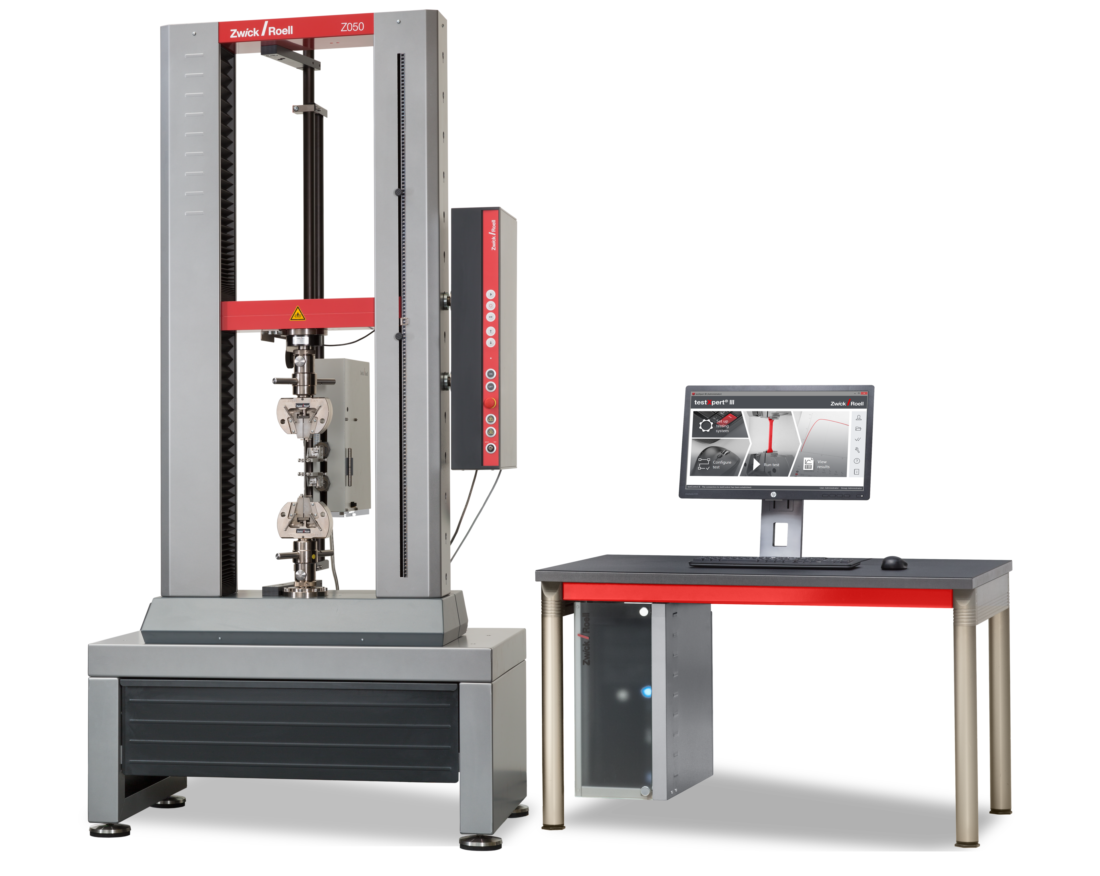
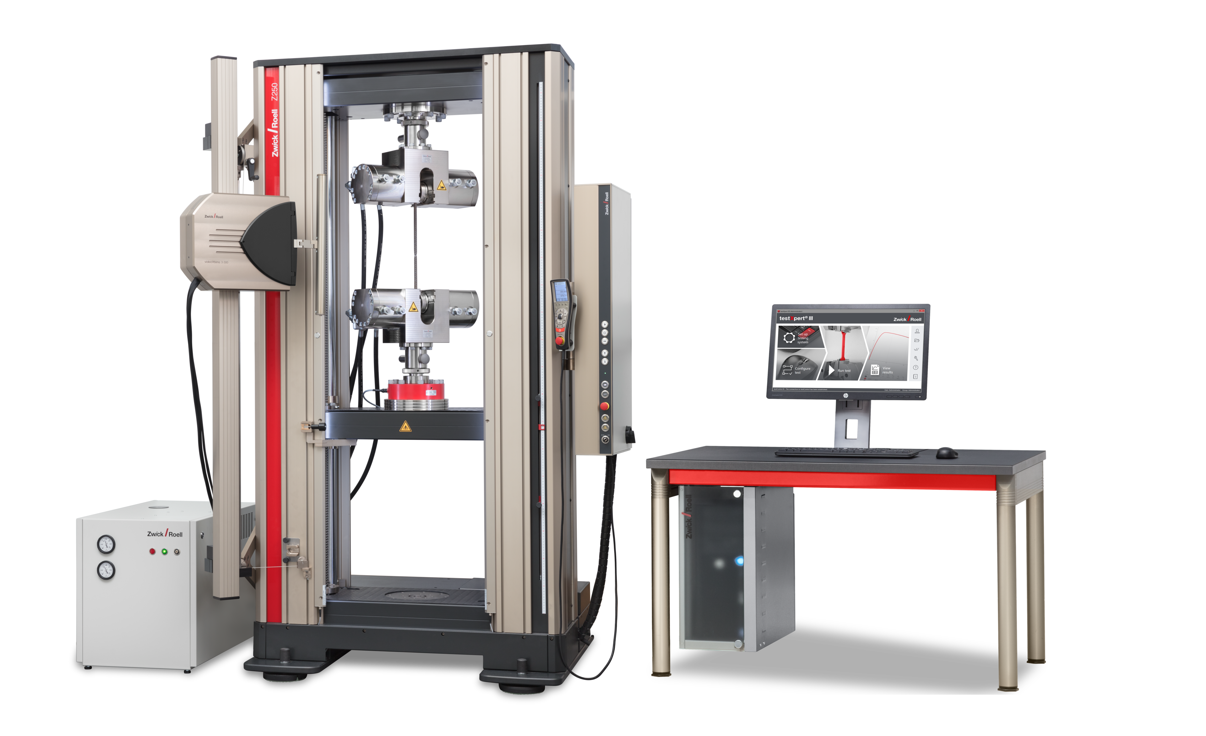
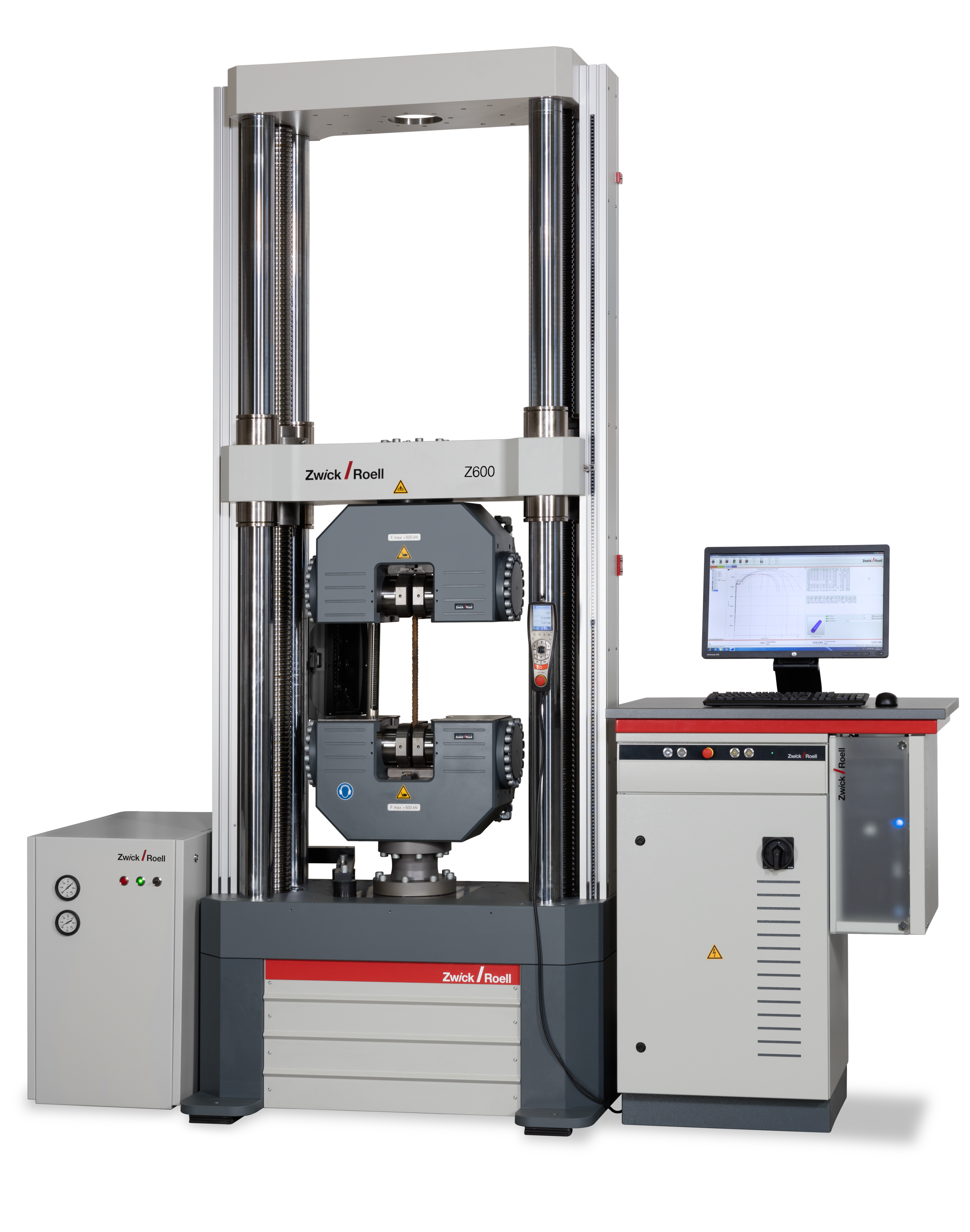
The selection of a testing machine is often reduced to the maximum required force range. In practice however, the right combination of load frames (universal testing machine), load cell, specimen grips/specimen mounts and extensometers determines whether tests can be performed efficiently and reproducibly. The selection process therefore begins with the expected force range of the specimens. Based on this, the appropriate load frame, suitable grips, and the optimal load cell are selected.
One advantage of ZwickRoell's modular testing system concept is that virtually any extensometer can be combined with almost any load frame. This allows the testing system to be flexibly adapted to different materials, specimen geometries, and standards requirements. At the same time, all load cells are calibrated to within 0.2% of their nominal force. For example, a 100 kN load cell can still measure precisely even with a test load of only 200 N. This enables both small and large specimens to be tested on the same materials testing machine compliant to standards and without compromising accuracy.

Gripping and aligning the specimen
When gripping the specimen, it is important to avoid bending, pre-stressing, and slippage.
For standard metals testing according to Method A (stress speed), wedge grips are a practical option and the most cost-effective solution in the portfolio. However, for Method B to ASTM E8/E8M, specimen grips with body-over-wedge principle or parallel-closing specimen grips are recommended to achieve the most reliable and reproducible test results.
With our Applications test laboratory and Xperience Center worldwide, experts are at your side who will find the right solution for your individual test task through individual consultation, on-site demonstrations and online support.

Test speed and selection of the control method
The test speed has a direct influence on the determined material properties. Especially with strain-rate-sensitive materials, different speeds can lead to different yield points, strain values, and strengths. ASTM E8 / ASTM E8M describes three control methods for this (more information on the control methods and their suitability can be found in the FAQs):
- Stress rate control (Method A)
- Strain rate control (Method B)
- Crosshead speed control (Method C)
ZwickRoell testing systems support all control methods described in the standard, thus enabling the standard-compliant implementation of a wide variety of testing requirements.
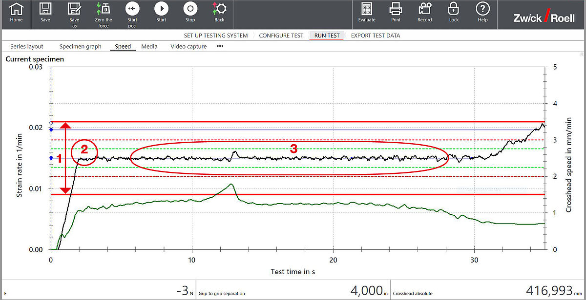
For the Method B preferred in the standard, ZwickRoell testing systems enable precise strain rate control in a closed-loop system. In conjunction with optical or contact extensometers, the actual strain rate is continuously monitored and automatically adjusted. While the standard allows comparatively large tolerances of +/- 20% in the strain rate (at a strain rate of 0.015 ± 0.006 in./in./min or mm/mm/min as specified by ASTM E8), ZwickRoell systems typically achieve an accuracy of 3% or better. This increases the reproducibility of the results and ensures that the selected test speed is reliably maintained even with different materials.
With our testXpert testing software, the strain rate is always traceable.
- The red line (1) shows the ASTM E8 defined tolerance range (40% of the set speed).
- The green dashed line represents the narrower tolerance range of 5%, which is the benchmark used by ZwickRoell testing systems to be on the safe side in the event of unforeseen events. Good strain rate control is characterized by (2) low inlet fluctuations and (3) stable speed control. An important requirement for this is an adaptive controller.
Selection of extensometers
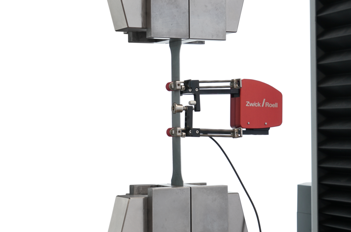
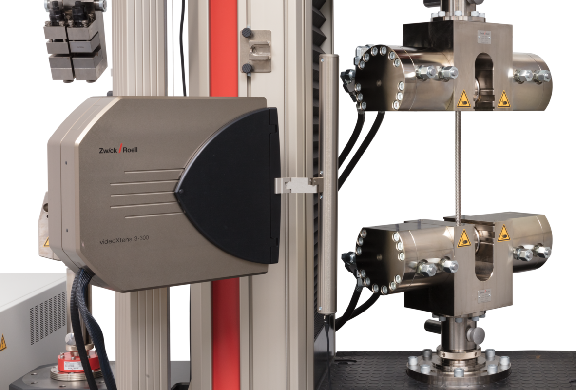
Strain measurement is one of the decisive influencing variables in the tensile test according to ASTM E8 / ASTM E8M. The standard allows different methods for determining elongation – from manual measurement of the elongation at break after the test, to contact extensometers (clip-on extensometer or makroXtens sensor arm extensometer) to optical extensometers (ideally with a mark-free solution such as videoXtens), which records the elongation without making contact throughout the entire test.
- The manual determination of the elongation at break after the test is associated with a comparatively high operator influence. Even small deviations when putting the fragments together or when reading the gauge length can influence the result.
- Contact extensometers provide precise elongation values during the test, but must be correctly positioned by the operator and can cause additional effort, especially with sensitive or small specimens.
ZwickRoell's preferred solution is optical extensometers.. They detect the elongation directly on the specimen without contact and independently of the operator.
- As a result, the gauge length and measuring position are clearly defined and reproducible at all times.
- At the same time, optical extensometers support the strain rate control according to Method B preferred by ASTM E8, since the elongation is recorded continuously and with high precision.
- Another advantage is that the strain distribution can be recorded over the entire specimen. This means that additional evaluations are still possible even after the test has been completed. In many cases, manual determination of the elongation at break can also be eliminated, which eliminates another potential source of error. This reduces operator influence, increases the reproducibility of the results, and simplifies day-to-day testing in the laboratory.
Video: Testing to ASTM E8 with ZwickRoell
Demonstration of the tensile test on metallic materials according to the standards ASTM E8 and ISO 6892-1:
- “Method B strain rate control closed loop” (corresponds to ISO 6892-1 Method A1) with ZwickRoell universal testing machine AllroundLine, contact extensometer makroXtens and non-contact extensometer videoXtens including specimen measurement and evaluation of the test results with testXpert
- "Method C crosshead speed open loop" (corresponds to ISO 6892-1 Method A2) with Proline universal testing machine and clip-on extensometer


Automation options to ASTM E8
Modern materials testing machines today achieve a very high level of accuracy. In many laboratories, therefore, it is no longer the testing machine itself that is the biggest cause of result variations, but rather the manual influence during the test sequence. Even small deviations in specimen identification, cross-section determination, specimen alignment or gripping can impair the reproducibility of the results.
Standardized and reproducible processes are crucial, especially when there are large numbers of specimen or when test data is used in quality control loops, process monitoring, or AI-based analyses. Automated testing systems reduce these influencing variables and ensure maximum reproducibility of all test steps.


Are you considering automated testing of metals?
ZwickRoell offers a wide range of automation solutions for this purpose – from micro and subsize specimens according to ASTM E8 to standard sheet metal specimens to automated high-capacity testing systems for heavy plate with test loads of up to 5 MN. In addition to greater reproducibility of the results, automation also improves occupational safety, especially with heavy specimens, and reduces the workload for laboratory personnel.
Learn more about automation options in metals testing Request your no-obligation consultation

ASTM E8 with testXpert testing software – efficient and reliable testing
With testXpert, you increase efficiency for tests to ASTM E8. And testXpert delivers reliable test results, the foundation for decisions you can count on.
- Regardless of the method you select, all the parameters specified by ASTM E8 are included in test program with 100% standard-compliance. In a preconfigured layout, you see the true achieved strain rate within the tolerances specified by the standard.
- Don’t spend unnecessary time on pre-tests and manual calculations for the strain rates according to ASTM E8. testXpert takes on automatic setting of all control parameters. Target positions and strain values are approached with pinpoint accuracy. Changes in specimen properties are compensated on line.
- testXpert ensures repeatable test results through identical test conditions via a predefined machine configuration.
- For reproducible test results, operator influence is reduced to a minimum, for example through our user management feature.
Typical applications for ASTM E8/ ASTM E8M
ASTM E8/E8M is one of the world's most important standards for the characterization of metallic materials and is aimed at manufacturers, processors, users and testing laboratories who require a standardized tensile test of metals at ambient temperature for material qualification, quality control, certification and engineering design:
- Material qualification of new metal alloys
- Quality control in metals production
- Incoming goods inspection of semi-finished products
- Acceptance tests in aerospace applications
- Materials development and research
- Proof of mechanical properties for customers and certification bodies
- Comparative testing between batches or production processes
- Process monitoring in series production
Frequently asked questions regarding ASTM E8
Strictly speaking, this ASTM standard includes two standards, and therefore ASTM E8 must be differentiated from ASTM E8M. While ASTM E8 refers to inch and pound units of measurement, ASTM E8M uses SI units. Because of this, values determined with one system of units are not exactly equal to those determined with the other system of units. In practice however, this usually does not present a problem, because there is no change between the units when determining and comparing characteristic values.
Within this context, it is however important to note that the initial gauge length for round specimens for the determination of strain in ASTM E8 refers to 4D, or four times the diameter of the round specimens, while in ASTM E8M it refers to 5D, or five times the diameter of the round specimens. A mix-up or failure to observe this difference can lead to characteristic values that are no longer comparable.
- Different test methods and definitions:Although both standards test the same material, characteristic values (e.g., elongation or yield point) are defined and evaluated differently – direct reproducibility is therefore limited.
- Different test speeds: ISO 6892-1 specifies test speeds precisely and depending on the material, while ASTM E8 allows greater tolerances – this can measurably influence the results.
- Different control methods and designations: The assignment of type of control (e.g., closed-loop strain rate control is designated to ASTM E8 as Method B and in ISO 6892-1 as Method A1) is named differently between ISO and ASTM, which often leads to confusion.
- Differences in specimen and measurement methods:Despite partially harmonized specimen geometries, details differ in dimensions, measurement uncertainties and cross-section measurement.
- Different determination of strain values: The determination of uniform elongation and elongation at break is performed according to different methods, which leads to differing results, especially for ductile materials.
- Different definitions of results: Terms such as tensile strength (Rm vs. TS) or strain values are not methodologically identical, even if they sound similar.
Brief summary: ISO 6892-1 and ASTM E8 are largely harmonized, but not identical – even small differences in methodology and evaluation can lead to significantly different test results.
You can find more information in our blog post ASTM E8 vs. ISO 6892-1 or in the webinar recording.
In short, the difference is:
- Elongation at break
This is the elongation at the exact moment when the specimen breaks. It is therefore recorded during the ongoing test, typically with an extensometer or optical measuring system. - Elongation after break
The elongation determined after the break by putting the broken specimen pieces back together and measuring the extension of the gauge length manually or optically.
Why is the distinction important?
The distinction in the normative context of ASTM E8 / E8M is important because elongation after break can depend more on operator influence and correct manual re-measurement, while elongation at break depends more on the measuring system used during the test. The values are therefore not automatically identical, especially for local necking, fracture position, manual feedback or different measurement methods.
There can be a wide range of shapes for tensile specimens. ASTM E8 / E8M lists standard flat specimens for sheet metal and thin sheets, for tubular products with large diameters, for special specimen grips, and standard round specimens, and specifies the corresponding initial gauge lengths to which all strain values refer. With a few exceptions, all dimensions that are needed for specimen preparation are specified, or else minimum dimensions are indicated (see Section 6 Test Specimens of ASTM E8/E8M-25).
Important information is provided for specimen preparation, which is intended to ensure that the sampling process and the subsequent specimen preparation do not influence the material, since this could in turn affect the results of the tensile test. All areas that were strain hardened through cutting or punching during the specimen machining process must be processed accordingly, if they have an effect on the specimen properties. Products with a constant cross section (profiles, bars, wires, etc.) and cast specimens
(e.g. cast iron, nonferrous alloys) can be tested without processing.
Standard flat specimens to ASTM E8/ E8M
| Specimen / material | Sheet thickness | Type of measurement | ASTM E8 | |
|---|---|---|---|---|
| Flat tensile specimen “Sheet type”* sheet metal, plates, flat wires, tapes, rectangles and profiles | 0.13 mm to 19 mm [0.005 in. to 0.750 in.] | Gauge length G | 50 mm [2.0 in.] | 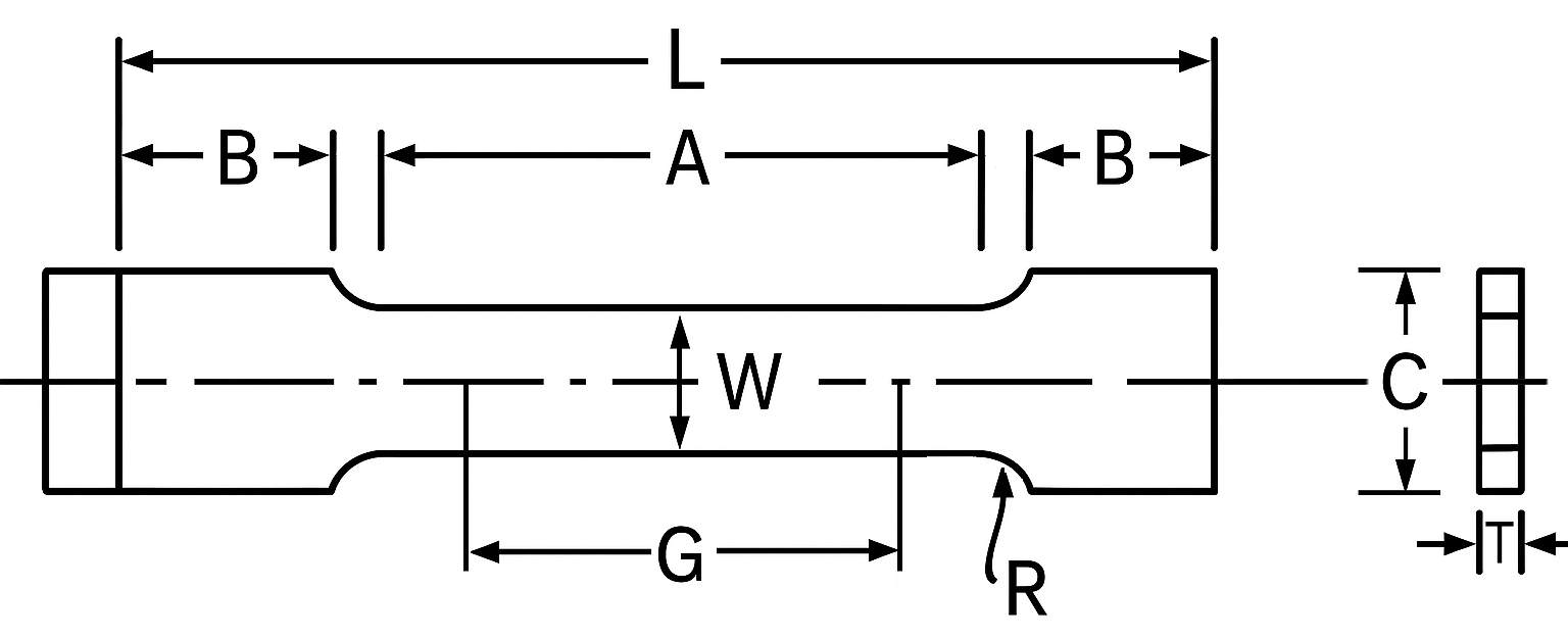 |
| Width (W) | 12.5 mm [0.5 in.] | |||
| Heavy plate specimen “Plate type” sheet metal, profile and flat material | min. 5 mm [0.188 in.] | Gauge length G | 200 mm [8.0 in.] | |
| Width (W) | 40 mm [1.5 in.] | |||
| Smallest specimen “Subsize specimen” | max. 6 mm [0.250 in.] | Gauge length G | 25 mm [1.0 in.] | |
| Width (W) | 6.0 mm [0.25 in.] |
* for materials with a thickness of up to 0.15 mm [0.0059 in.] the ASTM E345 standard is to be applied
* Tensile test specimen for pin loading can be used.To avoid buckling when testing thin and high-strength materials, it may be necessary to use stiffening plates at the ends of the jaws. (see Fig. 8, Section 6.3 Sheet type specimen ASTM E8/E8M-25)
Standard round specimens to ASTM E8 and E8M
| Specimens | Type of measurement | ASTM E8 (4x diameter) | ASTM E8M (5x diameter) | |
|---|---|---|---|---|
| Standard specimen “Specimen 1” | Gauge length G | 50.0 mm [2.000 in.] | 62.5 mm [2.500 in.] | 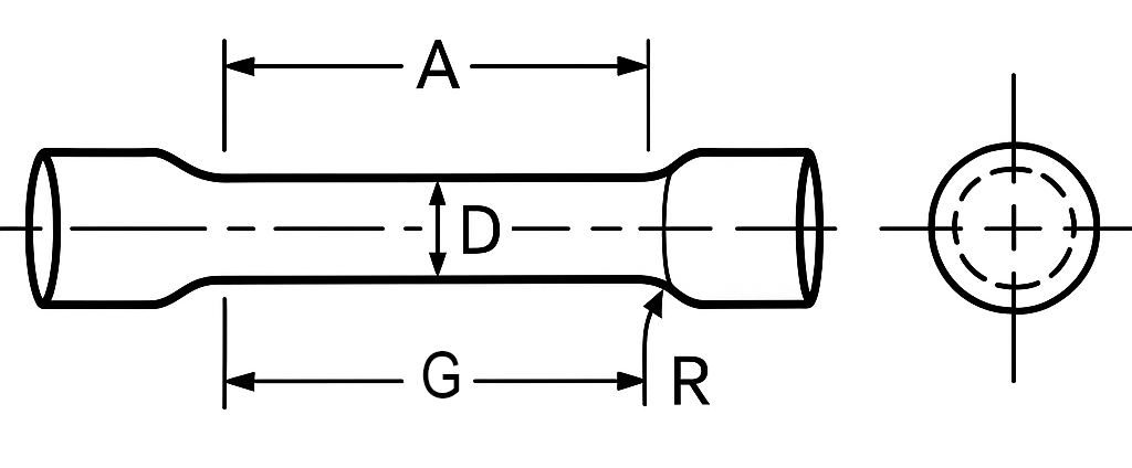 |
| Diameter D | 12.5 mm [0.500 in.] | |||
| Fillet radius R min. | 10.0 mm [0.375 in.] | |||
| Parallel length A (reduced section length) | 56.0 mm [2.25 in.] | 75.0 mm [3.0 in.] | ||
| Small-size specimen proportional to standard specimen | ||||
| “Specimen 2” | Gauge length G | 36.0 mm [1.400 in.] | 45.0 mm [1.750 in.] | |
| Fillet radius R min. | 8.0 mm [0.25 in.] | |||
| Diameter D | 9.0 mm [0.350 in.] | |||
| Parallel length A (reduced section length) | 45.0 mm [1.75 in.] | 54.0 mm [2.0 in.] | ||
| "Specimen 3” | Gauge length G | 24.0 mm [1.000 in.] | 30.0 mm [1.250 in.] | |
| Diameter D | 6.0 mm [0.250 in.] | |||
| Fillet radius R min. | 6.0 mm [0.188 in.] | |||
| Parallel length A (reduced section length) | 30.0 mm [1.25 in.] | 36.0 mm [1.4 in.] | ||
| "Specimen 4” | Gauge length G | 16.0 mm [0.640 in.] | 20.0 mm [0.800 in.] | |
| Diameter D | 4.0 mm [0.160 in.] | |||
| Fillet radius R min. | 4.0 mm [0.156 in.] | |||
| Parallel length A (reduced section length) | 20.0 mm [0.75 in.] | 24.0 mm [1.0 in.] | ||
| “Specimen 5” | Gauge length G | 10.0 mm [0.450 in.] | 12.5 mm [0.565 in.] | |
| Diameter D | 2.5 mm [0.113 in.] | |||
| Fillet radius R min. | 2.0 mm [0.094 in.] | |||
| Parallel length A (reduced section length) | 16.0 mm [0.625 in.] | 20.0 mm [0.75 in.] | ||
Particular focus is on the test speed. ASTM E8 and ASTM E8M support five different ways of specifying test speeds. They are designated as
- Specimen strain rate
- Specimen stress rate
- Crosshead speed
- The elapsed time for completing part or all of the test
- Free-running crosshead speed (rate of movement of the crosshead of the testing machine when not under load)
For determination of the so called yield properties, that is the yield strength, yield point elongation, and offset yield, in general all characteristic values related to the change of material behavior from elastic to plastic, it is important to define a suitable control of the test speed. Because in the case of metallic materials, these characteristic values can be significantly dependent on the actual test speed, and therefore the test speeds must be maintained within specified tolerances. ASTM E8 and ASTM E8M take this into account with three different control methods. They are designated as Method A, B and C.
Control method B:
Recommended method | Control method C:
| Control method A:
|
|
|
|
Method C is based on constant speed of the crosshead.
- The crosshead speed shall be set and kept constant so that the initial parallel length of the specimen undergoes an elongation of 0.015 ± 0.003 in./in./min or mm/mm/min.
- This method is recommended if the material does not deform continuously.
- Method C is intended for machines without digital controls or high-quality drive systems, but is no longer considered state of the art.
Method A is based on the increase in tensile stress during load application.
The decisive factor is that this is not a force-controlled test. Instead, the testing machine should be operated at a constant crosshead or actuator speed that generates a defined stress rate in the specimen (e.g., 11 MPa/s). Since the wording in the standard is sometimes unclear, this requirement is occasionally misinterpreted. In particular, it is mistakenly assumed that force control is required. However, the use of such force control can lead to significantly distorted and unusable test results.
- In the linear elastic part of the tensile test, that is at the very beginning of the test, the rate of stress application must be between 1.15 and 11.5 MPa/sec (this corresponds to 10000 and 100000 psi/min).
- However, it is clearly stated in ASTM E8 and ASTM E8M that these specifications and method do not imply that the stress increase should be held constant up to the point of plastic behavior or that closed loop control of the force increase may be applied beyond the linear elastic range.
- In practical application, Method A is used for standard metals with relatively stable elastic behavior, e.g., structural steels, quenched and tempered steels, or many non-ferrous metals, when a strain-controlled test arrangement is not available. However, the correct setting requires experience and a good knowledge of the system rigidity.
Method B is based on the control of the strain speed or strain rate (strain rate control) during the load application.
- The testing machine keeps the closed loop strain rate constant by using an extensometer to continuously provide strain values that are used to calculate the precise strain rate.
- The standard specifies a strain rate of 0.015 ± 0.006 in./in./min or mm/mm/min, which corresponds to a tolerance of 40% when setting the strain rate.
- It is considered the preferred method for almost all metallic materials, especially high-strength steels, aluminum alloys, titanium alloys, nickel-based alloys, and strain-rate-sensitive materials.
Strain rate control increases the reliability of test results and ensures reproducibility. The characteristic values of metallic materials are largely dependent on the strain rate. Usually, the higher the strain rate, the higher the strength values. Alloys and other product features also influence the strain rate dependence.
Special benefits are provided by closed loop strain rate control for which an adaptive controller is used to automatically maintain the correct strain speed:
- Time savings: the system automatically sets the correct strain rate, without user intervention.
- Simply reliable: this also eliminates errors when setting parameters
- Precision: an adaptive controller prevents overshooting of strain rates, keeping them constant and well within the tolerance range so that the strain rate also remains within tolerance limits in case of unforeseen events.
This method requires a control-technology-equipped testing system, which however significantly simplifies the test operation.


