ISO 7438 Bend Test on Metals
The bend test to ISO 7438 is a standardized method for determination of the bending properties of metallic materials. It supports the evaluation of the flexural strength and stiffness of a material.
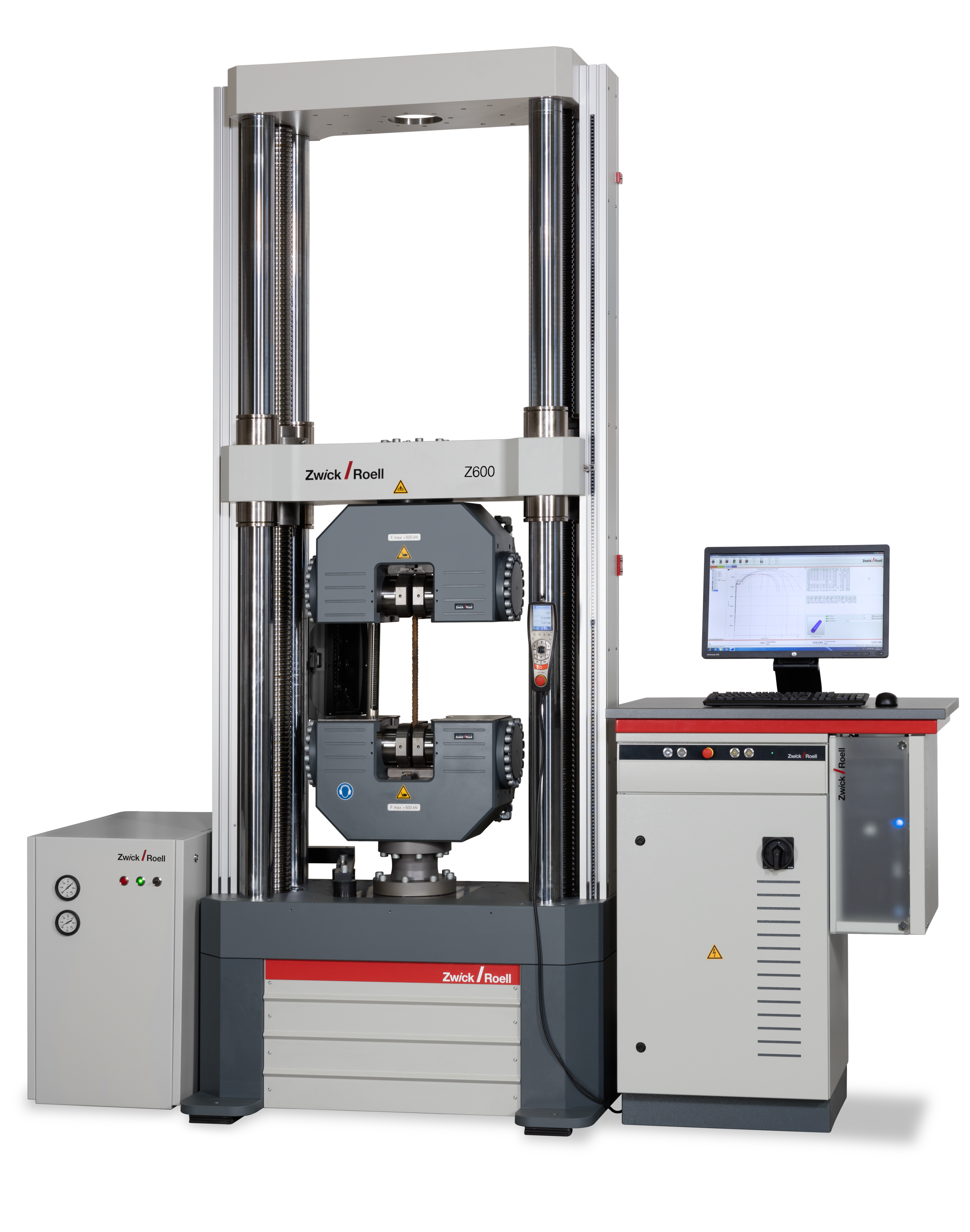
The bend test on metallic materials is performed as a 3-point bending test in which a specimen rests symmetrically on two supports and a perpendicular force is applied via a die to generate maximum flexural stress.
The following content explains the key aspects. For standard-compliant testing in accordance with ISO 7438, however, it is essential to purchase the complete standard.
Standards Specimens & bending angle Running the test Characteristic values Testing machines FAQ

Other standards for bend tests on metals
- ISO 8491 – Metallic materials – Tube (in full section) – Bend test
- ASTM A370 - Standard Test Methods and Definitions for Mechanical Testing of Steel Products
- ASTM E190 - Standard Test Method for Guided Bend Test for Ductility of Welds
- ASTM E290 - Standard Test Methods for Bend Testing of Material for Ductility
Specimens and bending angles for flexure test on metals
The specimen to be tested can have a round, square, rectangular or polygonal cross-section and the die deforms it plastically until a certain bending angle is reached:
- A defined bending angle (e.g. 90°)
- A bending angle of 180°, the specimen legs are parallel to each other at a fixed distance
- A bending angle of 180°, the specimen legs lie directly against each other
If the required bending angle is 180°, the specimen can be compressed using compression platens following the bending test.
Performing a test
With the force application from the die, the specimen is plastically deformed and bent. The contact surface of the specimen at the die is compressed and the opposite specimen surface is stretched. During the flexure test, tensile stress therefore occurs on one side of the specimen and compressive stress on the opposite side of the specimen.
Relative to the specimen cross-section, the stresses are greatest at the edges and are largely responsible for material failure. These maximum stresses on the edge are also referred to as bending stresses. When a yield strength or compressive yield strength of the material is reached, plastic yielding occurs.
When comparing the bend test to the tensile test or compression test, there is no homogeneous distribution of stress across the specimen cross-section. The material is equally affected by tensile and compressive forces. Therefore, different limiting stresses often apply to a material in the flexure test versus a tensile or compression test.
Normally, the flexure test is performed at ambient temperature.
Characteristic values of the bend test to ISO 7438
Material characteristic values resulting from the bend test according to ISO 7438 include maximum flexural stress, occurring deformations, breaking strength and resistance of the material. The test results provide important information about the flexural strength, also referred to as bend strength, and behavior of a material.

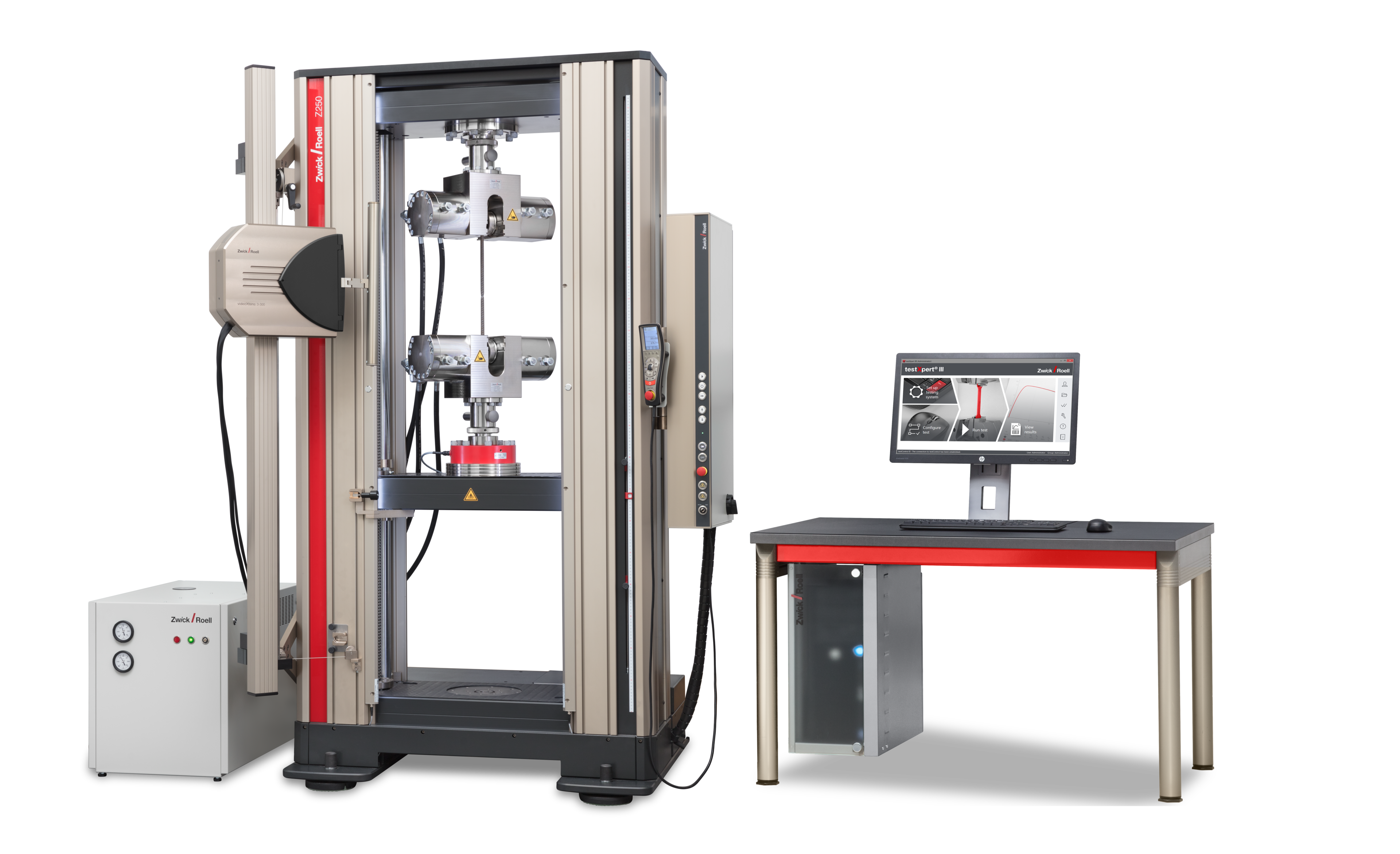


Take advantage of the leading testing software in materials testing
ZwickRoell’s testXpert testing software offers:
- Simple operation: start testing right away and be a testXpert while maintaining maximum safety.
- Reliable and efficient testing: benefit from reliable test results and maximum testing efficiency.
- Flexible integration: testXpert is the optimal solution for all of your applications and processes—simply put, a more effective workflow.
- Future-proof design: testing software for the entire life cycle, ready for your future test tasks!

FAQ
The bend test to ISO 7438 delivers material characteristic values such as maximum flexural stress, also known as bending stress, occurring deformations, breaking strength and resistance of the material.
Flexural stiffness, also known as flexural modulus or flexural elasticity module, is a characteristic value for the stiffness of a material under flexure loading. It indicates the ability of the material to resist bending stresses and maintain its shape.
The flexural stiffness of a material is calculated using the data from the bend test: Flexural stiffness = flexural stress / flexural deformation
Flexural strength (also maximum flexural stress or flexural breaking strength) indicates the maximum load the material can withstand under flexural loading
. It is typically presented as megapascals (MPa).
The flexural strength of a material is calculated using the data from the bend test: flexural strength = maximum bending force / cross-sectional area of the specimen