LTM electrodynamic testing machine
Download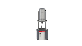
- 1 kN - 10 kN
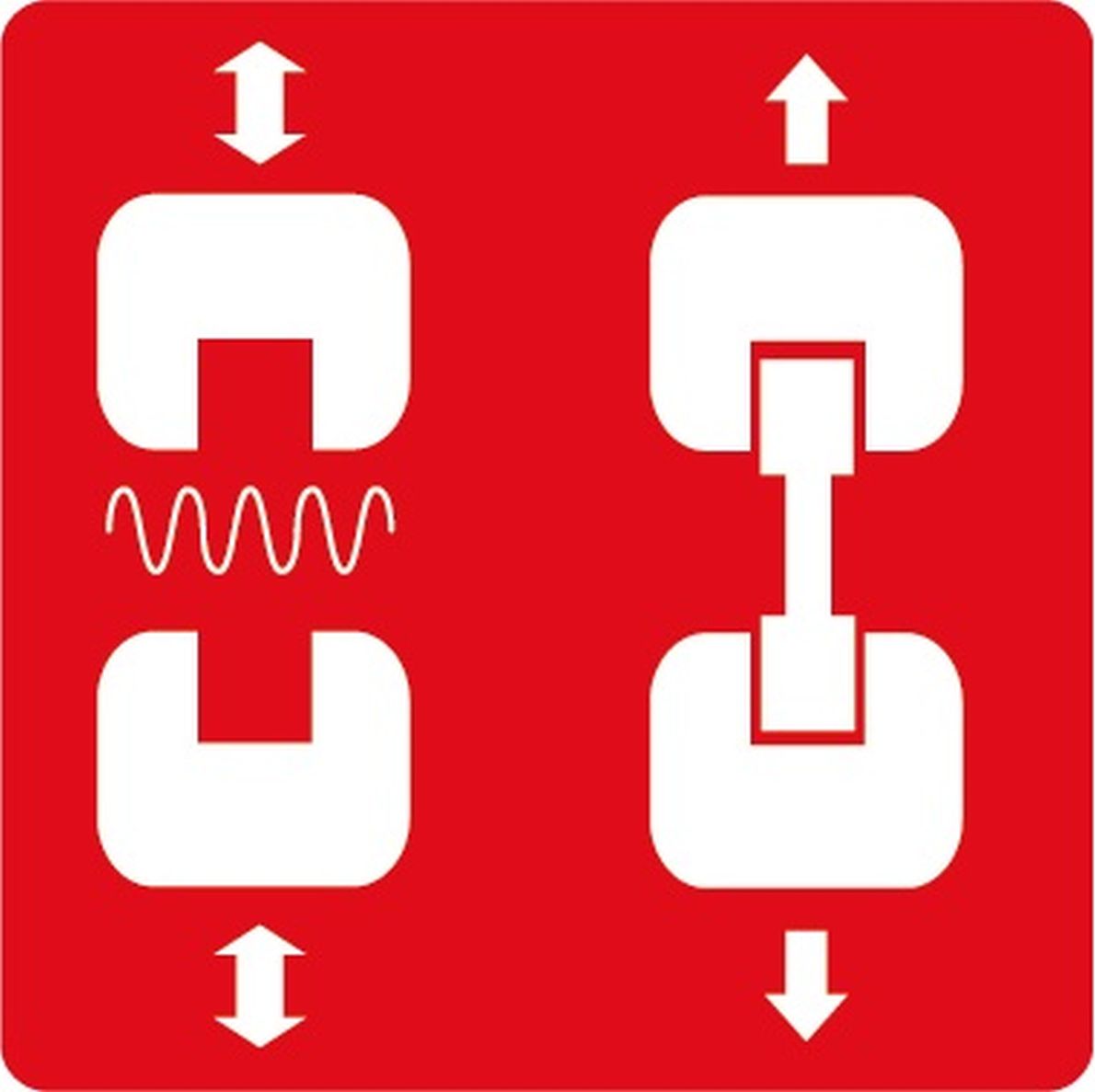
- Fatigue
- Tensile
- Compression
- ISO 18489
- ASTM F2193
- ISO 14801
- ASTM F1798
- ASTM F1717
The linear motor testing machine - an all around machine for the small force range
The LTM is an electrodynamic testing machine with a drive based on linear motor technology. The drive concept developed and patented by ZwickRoell enables the LTM to be used for both dynamic tests and static materials and components testing. The low moved mass of the drive provides ideal conditions for performing fatigue tests with tensile, compression, and flexural loading.
The LTM is available with loads of 1 kN, 2 kN, 3 kN, 5 kN and 10 kN.
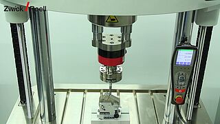
The LTM electrodynamic testing machine is used in industries where oil-free and low-noise drive technology are preferred, for example, in the medical industry for standard-compliant testing of hip joint, knee, or dental implants.
Other typical application examples include fatigue and durability tests on standard specimens made of plastics, fiber composites and metals.
For components testing, the LTM is equipped with a T-slotted platform that can be adapted to components, and test fixtures quickly and easily as standard.
Intuitive operation via our testXpert R and testXpert software makes the LTM a genuine all-rounder for industrial purposes, and for applications in research and as part of university curricula.


Technical overview
| Type | LTM 1 + 400 mm | LTM 1 HR + 400 mm | |
| Item No. | 1053558 | 3006626 | |
| Fmax, dynamic | ± 1000 | ± 1000 | N |
| Fmax, static continuous | ± 910 | ± 910 | N |
| Piston stroke | 60 | 60 | mm |
| Positioning accuracy and repeatability | ± 2 | ± 2 | μm |
| Speed range | 1 | 1 | mm/min |
| 1.5 | 2 | m/s | |
| Maximum frequency1 | 100 | 120 | Hz |
| Max. noise level at 1 m distance2 | < 61 | < 61 | dB(A) |
| Typical noise level at 1 m distance2 | < 45 | < 45 | dB(A) |
| Test frame | |||
| Overall height of testing machine, max. (A)3 | 1855 | 1855 | mm |
| Overall height of the testing machine with optional base, max. (E)3 | 2504 | 2504 | mm |
| Overall height of the test frame, max. (F) | 1306 | 1306 | mm |
| Overall height of the test frame with feet, max. (B) | 1345 | 1345 | mm |
| Overall width of the test frame | 665 | 665 | mm |
| Overall depth of the test frame | 525 | 525 | mm |
| Column diameter | 65 | 65 | mm |
| Frame stiffness at 500 mm crosshead separation | 40 | 40 | kN/mm |
| Height, base (G) | 692 | 692 | mm |
| Width, base | 800 | 800 | mm |
| Depth, base | 700 | 700 | mm |
| Overall weight4 | 270 | 270 | kg |
| Test area | |||
| Test area width | 460 | 460 | mm |
| Test area height without load cell, max. (D)35 | 1040 | 1040 | mm |
| Test area height with load cell, max. (C)35 | 950 | 950 | mm |
| Top crosshead adjustment | Motorized | ||
| Top crosshead clamping | Manual | ||
| Crosshead clamping electrically monitored | Yes, with signal indicator | ||
- Depending on load ratio (r-ratio) and test amplitude
- Depending on the output required, environment, test arrangement, type of test, frequency of the specimen, determined in free field according to DIN EN ISO 11205
- Highest crosshead position
- Testing machine only, without electrical cabinet, tools, and options
- Median piston position
| Type | LTM 2 + 400 mm | LTM 2 HR + 400 mm | |
| Item No. | 1053560 | 3006628 | |
| Fmax, dynamic | ± 2000 | ± 2000 | N |
| Fmax, static continuous | ± 1400 | ± 1400 | N |
| Piston stroke | 60 | 60 | mm |
| Positioning accuracy and repeatability | ± 2 | ±2 | μm |
| Speed range | 1 | 1 | mm/min |
| 1 | 2 | m/s | |
| Maximum frequency1 | 100 | 120 | Hz |
| Max. noise level at 1 m distance2 | < 61 | < 61 | dB(A) |
| Typical noise level at 1 m distance2 | < 45 | < 45 | dB(A) |
| Test frame | |||
| Overall height of testing machine, max. (A)3 | 1935 | 1855 | mm |
| Overall height of the testing machine with optional base, max. (E)3 | 2504 | 2504 | mm |
| Overall height of the test frame, max. (F) | 1306 | 1306 | mm |
| Overall height of the test frame with feet, max. (B) | 1345 | 1345 | mm |
| Overall width of the test frame | 665 | 665 | mm |
| Overall depth of the test frame | 525 | 525 | mm |
| Column diameter | 65 | 65 | mm |
| Frame stiffness at 500 mm crosshead separation | 40 | 40 | kN/mm |
| Height, base (G) | 692 | 692 | mm |
| Width, base | 800 | 800 | mm |
| Depth, base | 700 | 700 | mm |
| Overall weight4 | 270 | 270 | kg |
| Test area | |||
| Test area width | 460 | 460 | mm |
| Test area height without load cell, max. (D)35 | 1040 | 1040 | mm |
| Test area height with load cell, max. (C)35 | 950 | 950 | mm |
| Top crosshead adjustment | Motorized | ||
| Top crosshead clamping | Manual | ||
| Crosshead clamping electrically monitored | Yes, with signal indicator | ||
- Depending on load ratio (r-ratio) and test amplitude
- Depending on output required, the environment, test arrangement, type of test, frequency of the specimen, determined in a free field to DIN EN ISO 11205
- Highest crosshead position
- Testing machine only, without electrical cabinet, tools, and options
- Median piston position
| Type | LTM 3 + 170 mm | LTM 3 HR + 170 mm | |
| Item No. | 1053564 | 1058953 | |
| Fmax, dynamic | ± 3000 | ± 3000 | N |
| Fmax, static continuous | ± 2100 | ± 2100 | N |
| Piston stroke | 60 | 60 | mm |
| Positioning accuracy and repeatability | ± 2 | ± 2 | μm |
| Speed range | 1 | 1 | mm/min |
| 1 | 1.5 | m/s | |
| Maximum frequency1 | 100 | 120 | Hz |
| Max. noise level at 1 m distance2 | < 63 | dB(A) | |
| Typical noise level at 1 m distance2 | < 46 | dB(A) | |
| Test frame | |||
| Overall height of testing machine, max. (A)3 | 1930 | 1930 | mm |
| Overall height of the testing machine with optional base, max. (E)3 | 2590 | 2590 | mm |
| Overall height of the test frame, max. (F) | 1310 | 1310 | mm |
| Overall height of the test frame with feet, max. (B) | 1345 | 1345 | mm |
| Overall width of the test frame | 665 | 665 | mm |
| Overall depth of the test frame | 525 | 525 | mm |
| Column diameter | 65 | 65 | mm |
| Frame stiffness at 500 mm crosshead separation | 40 | kN/mm | |
| Height, base (G) | 692 | 692 | mm |
| Width, base | 800 | 800 | mm |
| Depth, base | 700 | 700 | mm |
| Overall weight4 | 310 | 310 | kg |
| Test area | |||
| Test area width | 460 | 460 | mm |
| Test area height without load cell, max. (D)35 | 1040 | 1040 | mm |
| Test area height with load cell, max. (C)35 | 950 | 950 | mm |
| Top crosshead adjustment | Motorized | ||
| Top crosshead clamping | Manual | ||
| Crosshead clamping electrically monitored | Yes, with signal indicator | ||
| Max. noise level at 1 m distance6 | < 63 | ||
| Typical noise level at 1 m distance6 | < 46 | ||
| Frame stiffness at 500mm crosshead separation | 40 | ||
- Depending on load ratio (r-ratio) and test amplitude
- Depending on output required, the environment, test arrangement, type of test, frequency of the specimen, determined in a free field to DIN EN ISO 11205
- Highest crosshead position
- Testing machine only, without electrical cabinet, tools, and options
- Median piston position
- Depending on the output required, environment, test arrangement, type of test, frequency of the specimen, determined in free field according to DIN EN ISO 11205
| Type | LTM 5 Standard | LTM 5 + 250 mm1 | LTM 10 Standard | LTM 10 + 250 mm1 | |
| Item No. | 1008107 | 3001848 | 1008108 | 3001847 | |
| Fmax, dynamic | ±5 | ± 5 | ± 10 | ± 10 | kN |
| Fmax, static continuous | ±3.5 | ± 3.5 | ± 7 | ± 7 | kN |
| Piston stroke | 60 | 60 | 60 | 60 | mm |
| Positioning accuracy and repeatability | ±2 | ±2 | ± 2 | ±2 | μm |
| Speed range | 1 | 1 | 1 | 1 | mm/min |
| 1.5 | 1.5 | 1.0 | 1.0 | m/s | |
| Maximum frequency2 | 100 | 100 | 100 | 100 | Hz |
| Max. noise level at 1 m distance3 | < 68 | < 68 | < 68 | dB(A) | |
| Test frame | |||||
| Overall height of testing machine, max. (A)4 | 2510 | 2760 | 2715 | 2965 | mm |
| Overall height of the test frame, max. (B) | 1980 | 2230 | 1980 | 2230 | mm |
| Overall width | 860 | 860 | 860 | 860 | mm |
| Overall depth | 850 | 850 | 850 | 850 | mm |
| Height of mounting table (C) | 720 | 720 | 720 | 720 | mm |
| Column diameter | 65 | 65 | 65 | 65 | mm |
| Frame stiffness at 1000mm crosshead separation | 300 | 300 | 300 | 300 | kN/mm |
| Overall weight5 | 941 | 966 | 1040 | 1065 | kg |
| Test area | |||||
| Test area width | 460 | 460 | 460 | 460 | mm |
| Test area height, max. (D)4 | 1106 | 1356 | 1106 | 1356 | mm |
| Test area height without load cell, max. (E)46 | 920 | 1170 | 920 | 1170 | mm |
| Test area height with load cell, max. (F)46 | 781 | 1031 | 781 | 1031 | mm |
| Top crosshead adjustment | Motorized | ||||
| Top crosshead clamping | Manual | ||||
| Crosshead clamping electrically monitored | Yes, with signal indicator | ||||
| Max. noise level at 1 m distance7 | < 68 | ||||
- Extended load frame - required for use with a temperature chamber
- Depending on load ratio (r-ratio) and test amplitude
- Depending on output required, the environment, test arrangement, type of test, frequency of the specimen, determined in a free field to DIN EN ISO 11205
- Highest crosshead position
- Testing machine only, without electrical cabinet, tools, and options
- Median piston position
- Depending on the output required, environment, test arrangement, type of test, frequency of the specimen, determined in free field according to DIN EN ISO 11205
| testControl II measurement and control electronics | ||
| Control frequency | 10 kHz | |
| Measured-value acquisition | 10 kHz, 24 bits, arithmetical | |
| Slots | 5 x module bus | |
| PC interface | GigaBit Ethernet | |
| Integrated safety concept | - Two-channel specification for maximum safety | |
| - Interface for interlocked safety doors | ||
| - Emergency Stop link interface | ||
| Display-equipped remote control | - Setup or testing mode | |
| - Emergency Stop button | ||
| - Key switch for switching between setup and testing modes | ||
| Dimensions | ||
| Height | 750 | mm |
| Width | 600 | mm |
| Depth | 600 | mm |
| Weight, approx. | 102 | kg |
| Length of cable between LTM & testControl II | 500 | mm |
| Protection class | IP 54 | |


testXpert R – our software for dynamic testing
testXpert R is used with servohydraulic testing machines, vibrophores and electrodynamic testing machines. The testing software offers the right test programs for fatigue tests, fracture mechanics, low cycle fatigue (LCF). A graphical block editor is available for free test configurations, where up to 100 blocks can be parameterized.


Downloads
- Product Information: LTM 1 / LTM 1 HR PDF 1 MB
- Product Information: LTM 2 / LTM 2 HR PDF 1 MB
- Product Information: LTM 3 / LTM 3 HR PDF 1 MB
- Product Information: LTM 5 / LTM 10 PDF 742 KB
- Product Information: LTM 1-3 with Torsion Drive PDF 444 KB
- Product Information: LTM 5-10 with Torsion Drive PDF 714 KB
- Product Brochure: Dynamic and Fatigue Testing Systems PDF 5 MB


