ASTM F1717, ASTM F2706, ISO 12189 Tests on Screw and Rod Systems for the Spine
The ASTM F1717, ASTM 2706 and ISO 12189 standards describe various methods for testing screw and rod systems for the spine. This mechanical investigation under static and dynamic load is an important part of R&D and acceptance tests.
The implants are mounted on a vertebral body replacement test block made of ultra-high molecular weight polyethylene (UHMWPE). The use of simulated vertebral bodies improves test reproducibility when compared to using human preparations.
Screw and rod systems are used to stabilize the spine. For this purpose, adjacent vertebrae are connected with the help of screws, hooks, rods or plates and thus permanently fixed in place.
ASTM F1717
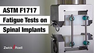
ASTM F1717, “Standard Test Methods for Spinal Implant Constructs in a Vertebrectomy Model” describes static test methods and methods for fatigue tests on spinal implants in a vertebrectomy model.
A vertebrectomy is considered the worst case scenario. Therefore, the spinal implant assembly is tested in this least favorable test configuration (vertebrectomy model). The spinal implants are mounted on two test blocks made of ultra-high molecular weight polyethylene (UHMWPE). The gap between the test blocks is defined and simulates the absence of a vertebral body.
The following test methods are described in detail in the standard.
ASTM F2706
ASTM F2706, “Standard Test Methods for Occipital-Cervical and Occipital-Cervical-Thoracic Spinal Implant Constructs in a Vertebrectomy Model” describes static test methods for fatigue tests on occipital-cervical and occipital-cervical-thoracic spinal implants in a vertebrectomy model.
The vertebrectomy is considered the worst case scenario. Therefore, the spinal implant assembly is tested in this least favorable test configuration (vertebrectomy model). For the test, the spinal implant construct is mounted on two (superior and inferior) polyacetal test blocks. The gap between the test blocks is defined and simulates the absence of a vertebral body.
The following test methods are described in detail in the standard.
ISO 12189
ISO 12189, “Implants for surgery — Mechanical testing of implantable spinal devices — Fatigue test method for spinal implant assemblies using an anterior support”, describes fatigue testing on flexible spinal implants, especially semi-rigid and dynamic implant assemblies using an anterior support. This test standard is intended for spinal implant assemblies that cannot be tested according to the test method described in ASTM F1717.
The spinal implant to be tested is firmly mounted on test blocks made of ultra-high molecular weight polyethylene (UHMWPE). The number of test blocks used simulate the vertebrae. The type and number of test blocks depends on the position of the vertebrae to be simulated. Between the test blocks, springs with specified stiffness values simulate the intervertebral discs and provide the additional anterior support as specified in ASTM F1717.
The tests are carried out under sinusoidal load with a maximum test frequency of 5 Hz. The force is in turn dependent on the spinal column position that is to be simulated. (lumbar: 0.6-2.0 kN / cervical: 0.05-0.15 kN). The test ends when 5 million load cycles have been reached or when the construct undergoes mechanical failure. The results of the fatigue test must be summarized in an S-N curve. The tests are performed at ambient temperature, but can also be repeated in Ringer’s solution at 37 °C if necessary, to simulate physiological environmental conditions and determine possible corrosion effects.


Static compression bending test to ASTM F1717 and ASTM F2706
The spinal implant construct is clamped in a test fixture and a compression force of max. 25 mm/min is applied. The force-displacement curve is recorded and evaluated in terms of the mechanical properties. Related test results are
- Displacement at 2% offset yield (mm)
- Compressive bending yield load (N)
- Compressive bending stiffness (N/mm)
- Compressive bending ultimate load (N)
- Compressive bending ultimate displacement (mm)

Static tensile bending test to ASTM F1717 and ASTM F2706
The spinal implant construct is clamped in a test fixture and a tensile force of max. 25 mm/min is applied. The force-displacement curve is recorded and evaluated in terms of the mechanical properties. Related test results are
- Displacement at 2% offset yield (mm)
- Tensile bending yield load (N)
- Tensile bending stiffness (N/mm)
- Tensile bending ultimate load (N)
- Tensile bending ultimate displacement (mm)


Static torsion test to ASTM F1717 and ASTM F2706
The spinal implant construct is clamped in a test fixture and a torsional load of max. 60°/min is applied. The torque-angular displacement curve is recorded and evaluated in terms of the mechanical properties.
Related test results are
- Angular displacement at 2% offset yield (degrees)
- Elastic angular displacement (degrees)
- Yield torque (N-m)
- Torsional stiffness (N-m/degree)
Dynamic compression bending fatigue test to ASTM F1717 and ASTM F2706
The dynamic compression bending fatigue test is performed after the static tests. The tests are performed with new specimens under sinusoidal load and a constant ratio of maximum to minimum force of R ≥ 10 with a maximum of 5 Hz. The initial fatigue load is either based on the user’s experience or can have a starting point of 75 %, 50 % or 25 % of the yield load. The test ends when 5 million load cycles have been reached or when the construct undergoes mechanical failure.
To determine the endurance limit, the difference between the lowest load that leads to failure must not be greater than 1.25 times the highest load at which it survives. The results of the fatigue test must be summarized an S-N curve. The tests are performed at ambient temperature, but can also be repeated in Ringer’s solution at 37 °C if necessary, to simulate physiological environmental conditions and determine possible corrosion effects.

Dynamic torsion test to ASTM F2706
The dynamic torsion test is also carried out with test blocks made of polyacetal. The spinal implant construct is loaded with a constant ratio of maximum to minimum load of R=1. The test ends when 5 million load cycles have been reached or when the construct undergoes mechanical failure. The test frequency shall be a maximum of 5 Hz. The results are documented and the fatigue strength is determined in the same way as for the dynamic compression and/or shear test.

Test fixtures for testing to ASTM F1717 and ASTM F2706
Depending on the intended mounting position (lumbar or cervical) and the installed components of the spinal implant assembly (rods, screws, hooks, cables or wire), ZwickRoell offers different test fixtures to meet the test methods required by standards ASTM F1717 and ASTM F2706.
The implant to be tested is attached to a special test block pair and mounted in the specimen grip. The ease with which the test blocks can be interchanged enables a high degree of flexibility and reduces acquisition costs.
All test fixtures can be used for both static and dynamic tests. Each setup contains one pair of corresponding UHMWPE or polyacetal test blocks.
A compensating bearing enables free rotation around the Z-axis as required by the ASTM F1717 and F2706 standards for tensile, compression and fatigue testing. This bearing can also be used for tensile, compression and axial fatigue testing for both standards.


The ZwickRoell test fixture for ISO 12189 testing contains all compression dies, test blocks and springs with the required spring stiffness and is therefore immediately ready for use.
All the test fixtures are made of stainless steel so that in addition to testing at ambient temperature, testing under physiological (in vitro) conditions is also possible with use of the ZwickRoell temperature-controlled bath.


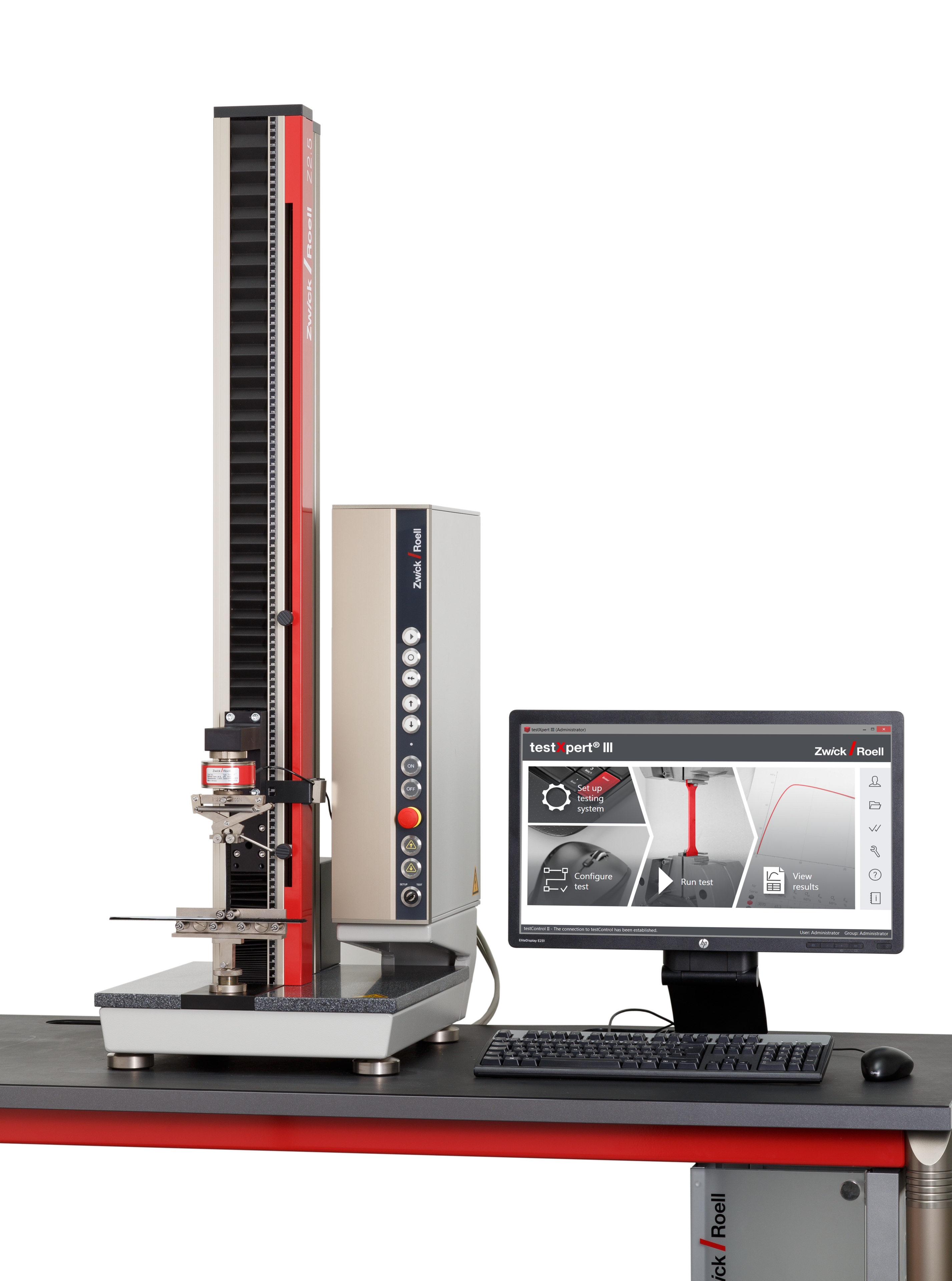
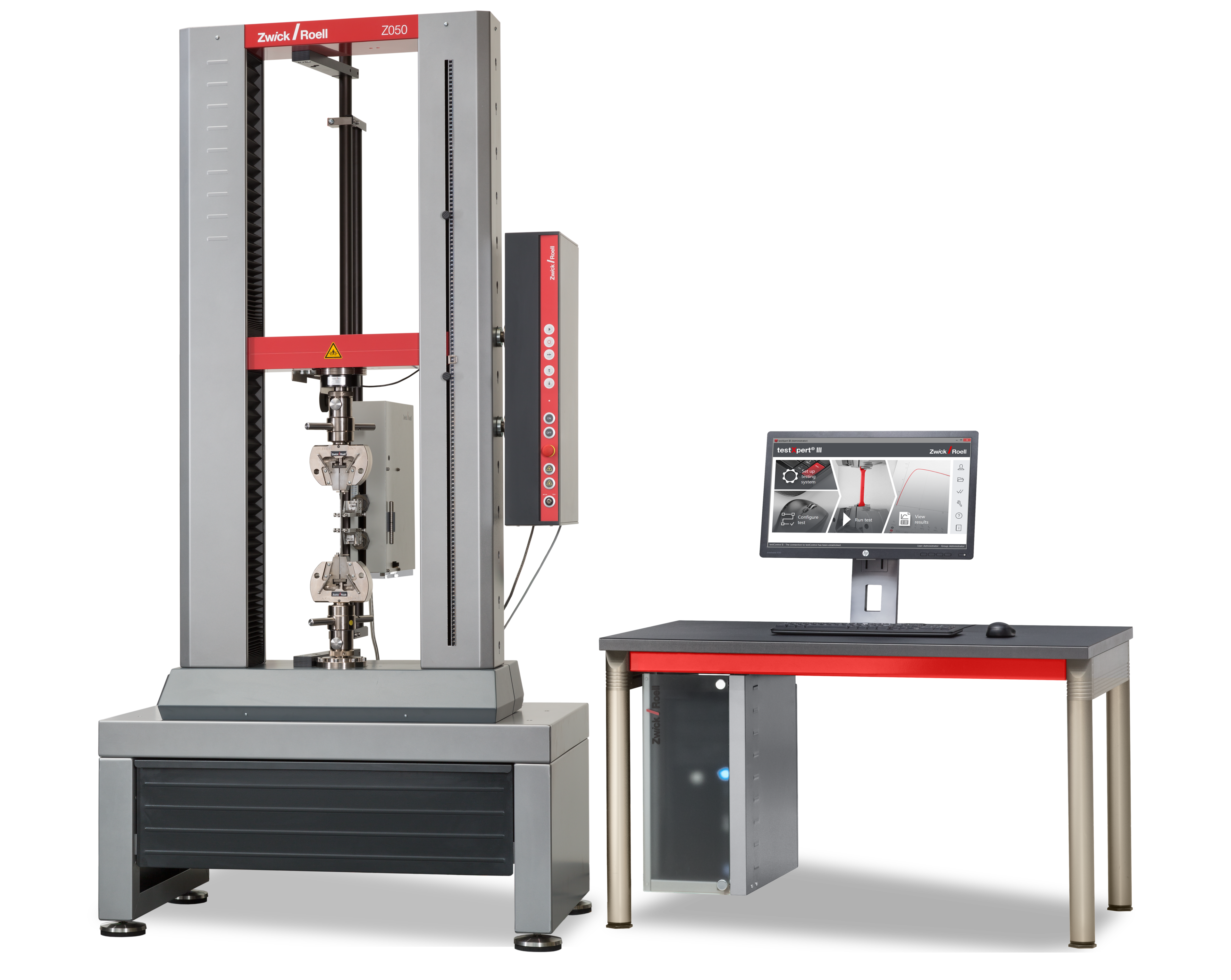
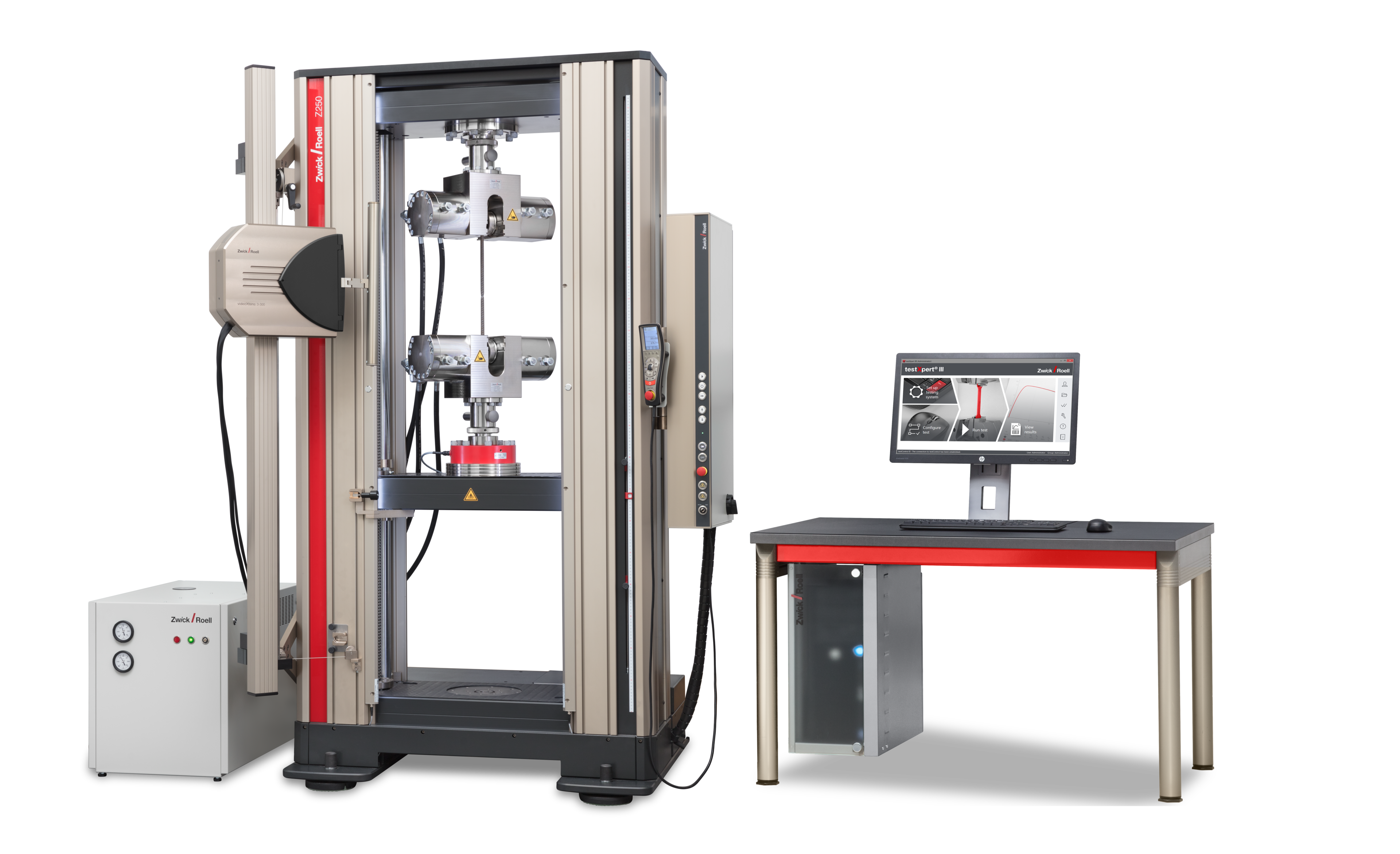
Related testing machines
Due to the different static and dynamic test methods, a variety of ZwickRoell testing systems can be considered. These range from a static zwickLine, ProLine or AllroundLine materials testing machine to an electrodynamic or even servohydraulic testing machine type LTM or HC with torsion.
The table below can be referenced to select the right testing system.
| Static | Dynamic and Fatigue Testing Systems | ||||
|---|---|---|---|---|---|
| Tensile/compression/bending | Torsion/bending | Tensile/compression/bending | Torsion | ||
| ASTM F1717 | • | • | • | - | |
| ASTM F2706 | • | • | • | • | |
| ISO 12189 | - | - | • | - | |
| Related products | |||||
| LTM Torsion HC Torsion | • | • | • | • | |
| LTM HC Compact | • | - | • | - | |
| zwickiLine ProLine AllrondLine | • | • | - | - | |
| zwickiLine AllroundLine Torsion drive | • | - | - | - | |
testXpert R enables static as well as dynamic testing of spinal implants. The software solution provides a suitable standard test program for the respective application, reflecting the requirements of the standard. This allows you to run standard-compliant tests with just a few clicks. The design of all test programs is workflow-based and mirrors a lab’s operating processes so that the user is guided through the test in logical steps.
The testXpert R standard industry packages include all important standards and test methods specific to the spinal implant (screw and rod systems) industry segment, with guaranteed standard compliance. They provide the ideal solution for different standard tests within an industry.