Flexure testing
Along with the tensile test and the compression test, the flexure test is one of the most frequently used types of loading. The flexure test (also referred to as bending test) therefore has great significance in testing a wide range of materials, and is used for the determination of mechanical material characteristics of metals, plastics, wood, paper, cardboard, ceramics and more. Flexure tests are also used in the areas of quality control and research and development of medical products, including the break resistance of injection needles, flexural strength of medical tubing and catheters, the strength of bone plates, and much more.
Flexure test characteristic values are generally obtained via the 2-point flexure test, 3-point flexure test or 4-point flexure test.
Characteristic values2-point flexure test3-point flexure test4-point flexure test
We are always available to provide you with more information about our testing solutions for standardized compression tests according to ISO, ASTM and others in the various industries:

Why flexure tests?
Flexure tests are performed to determine important mechanical characteristics. In particular, this test is used for tests on brittle materials, since the specimen causes metrological problems during the tensile test due to its failure behavior.
What can you determine using a flexure test?
Depending on the material, different material properties can be determined. The results or characteristic values of the flexure test show, in particular, the material behavior near the surface of the specimen. The deflections measured are approximately four times greater than the extensions in a tensile test.
Typical test results/characteristic values are:
- Strength testing of materials
- Calculation of the flexural stress and strain
- Flexural modulus
- Bending stiffness
- Flexural resistance
- Stress at 3.5 % elongation
- Stresses and elongations at the yield point and at specimen break
- etc.

2-point flexure test kits
In the 2-point flexure test, the specimen is gripped at one end and loaded with a test die on the exposed side.
The 2-point flexure test kit from ZwickRoell is suitable for cardboard and paper testing, as well as film testing. The bending stiffness or bending resistance of paper, cardboard and paperboard is determined in accordance with DIN 53121, ISO 5628 and DIN 19304, for example.
ZwickRoell also offers special 2-point flexure test kits for testing of injection needles to ISO 9626, determination of the kink resistance of guidewires, or the flexural strength of stiffer medical tubing (catheters, etc.).


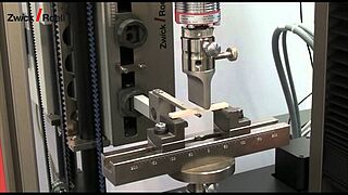
3-point flexure test kit
The loading device consists of two parallel-positioned anvils for the specimen and an upper anvil positioned centrally between the anvils. The upper anvil applies the load to the specimen.
Depending on requirements (standard), the anvils and upper anvils must have fixed, rotating or rocking mountings to enable testing in accordance with specifications.
The test is mainly used for tough and elastic materials.
To minimize frictional influences during testing the anvils can be mounted so as to rotate around their longitudinal axis. Rocking mountings can be used with the upper anvil and anvil supports to ensure that they are parallel to the specimen.


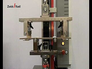
4-point flexure test kit
As with the 3-point flexure test, the 4-point flexure test kit consists of two parallel-positioned anvils which, depending on the test requirements, must have fixed, rotating or rocking mountings.
The difference from the 3-point flexure test lies in the way in which the load is applied to the specimen. This is done via 2 upper anvils located symmetrically to the anvils. The bending moment is then constant between the two force application areas.
This test is primarily used to determine the modulus of elasticity in bending for brittle materials.
The Dynstat flexure and impact bending test to DIN 53435 is used in the characterization of material properties for components made of plastics if, for example, only relatively small specimens can be taken from finished injection molded parts due to space constraints.


Flexure tests according to standardized test methods of various industries
| Short description | Standards |
|---|---|
| Paper, cardboard & corrugated board | Flexure test / stiffness under flexure (2-point, 3-point, 4-point) |
|
| Construction materials | Wood | Tensile and flexure test |
|
| Medical | Dental industry | Flexural strength ceramics |
|
| Plastics | Components | Dynstat test |
|
| Composites | Flexure tests |
|
| Plastics | 3-point flexure test |
|
| Plastics | 3-point flexure test |
|
| Metals | Flexure test |
|
| Metals | Concrete-reinforcing steel | Tensile, flexure and fatigue test |
|
| Medical | Bone plates | Flexural strength |
|
| Medical | Cannulas & needles | Break resistance |
|