Specimen Grips and Test Tools for Materials Testing
Holding the specimen using suitable specimen grips and test tools is an elementary prerequisite for reliable testing with accurate test results.
With a wide range of specimen grips of different designs, test load ranges and test temperatures, ZwickRoell not only covers the major application areas such as plastics, composites and metals testing, but also offers other industries such as medical and pharmaceuticals, textiles, food & packaging and paper & cardboard highly up-to-date and standard-compliant solutions for a wide range of specimen materials and specimen shapes.
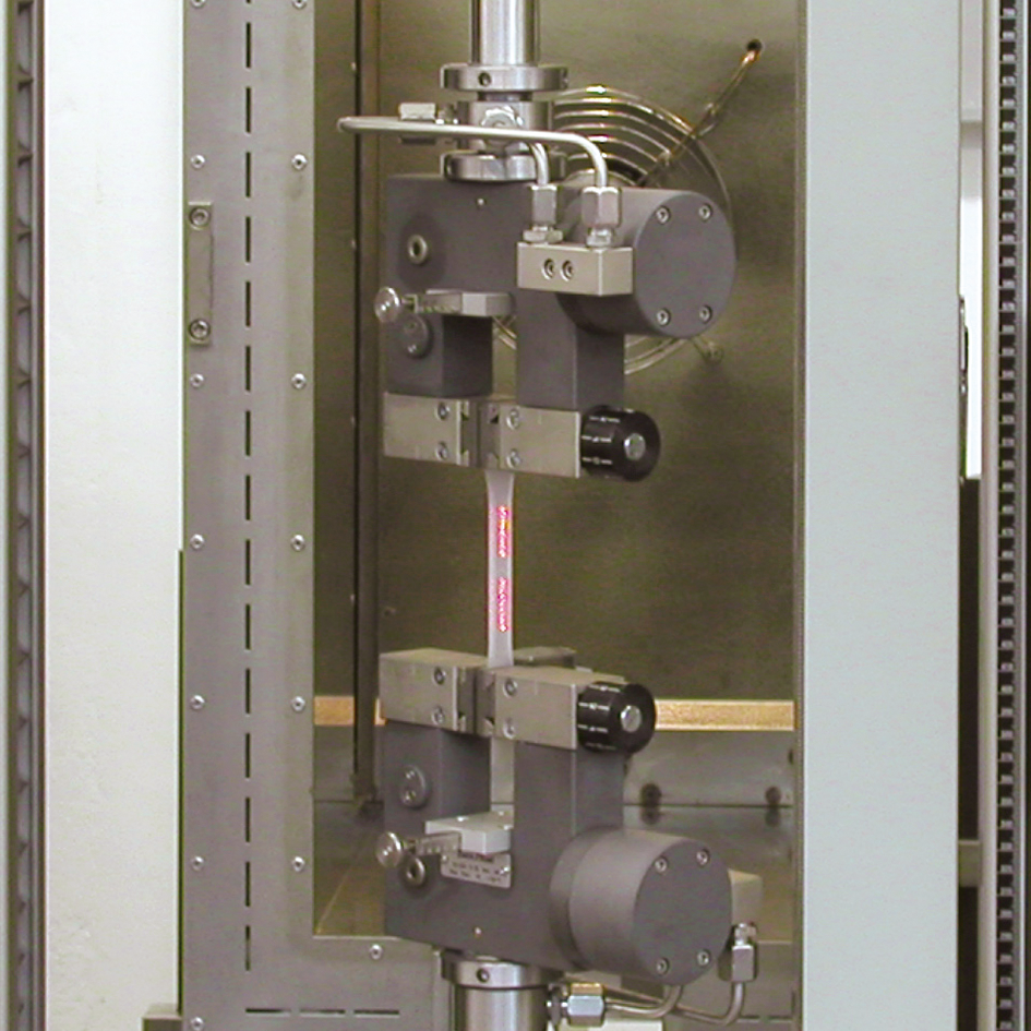
The most commonly used test is the tensile test. It places particularly high demands on the specimen grips because the test force is not directed vertically onto the specimen - as in compression and flexure tests - but acts in the exact opposite direction. The tensile specimen therefore always requires corresponding protrusions at its ends (heads) to transfer the test load to the specimen grips.
ZwickRoell also offers a wide range of specimen grips and test fixtures for compression and flexure tests.

Selection criteria for tensile specimen grips
| Specimen grip (operating principle) | Sizes (max. test load) | Temperature application range | Main areas of application | |
|---|---|---|---|---|
 | Screw grips | 0.02-50 kN | -70° … +250° | Plastic films, strip specimens, tapes, ropes, cords, shoulder rods, sheets and thin sheets, wires, fine wires, tapes, tubes, shoulder, flat and round specimens, textile fibers, yarns, nonwovens, conveyor belts, belts |
 | Spring-loaded grips | 0.02-0.05 kN | -15° … +80° | Plastic films, wires, fine wires, textile fibers, fine yarns, elasto yarns, clamp-sensitive material |
 | Pneumatic grips | 0.02-100 kN | -70° … +250° | Plastic films, strip specimens, tapes, monofilaments, ropes, cords, shoulder rods, sheets and thin sheets, wires, fine wires, tapes, tubes, shoulder, flat and round specimens, yarns, nonwovens, general and technical fabrics, cords, ropes, ropes, conveyor belts, belts |
 | Hydraulic grips | 10-2,500 kN | -70° … +250° | Plastic tapes, monofilaments, shoulder rods, sheets and thin sheets, wires, fine wires, tapes, tubes, shoulder, flat and round specimens, profiles, nonwovens, general and technical fabrics, geotextiles, conveyor belts, belts |
 | Wedge grips | 2.5-600 kN | -70° … +250° | Monofilaments, shoulder rods, sheets and thin sheets, wires, fine wires, tapes, tubes, shoulder, flat and round specimens, conveyor belts, belts |
 | Wedge screw grips | 0.5-250 kN | -40° … +250° | Plastic shoulder rods, sheet metal and thin sheet metal, wires, fine wires, strips, tubes, shoulder, flat and round specimens, conveyor belts, belts |
 | Pincer grips | 0.5-10 kN | -40° … +250° | Plastic films, strip specimens, sheet metal and thin sheet metal, flat specimens, conveyor belts, belts |
 | Toggle grips | 0.3-2.5 kN | -15° … +80° | Plastic films, strip specimens, nonwovens |
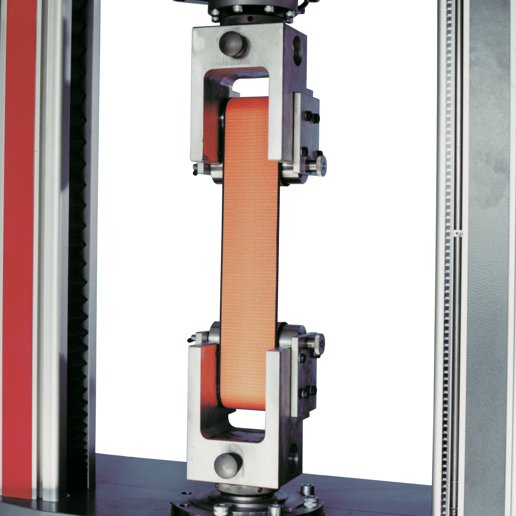
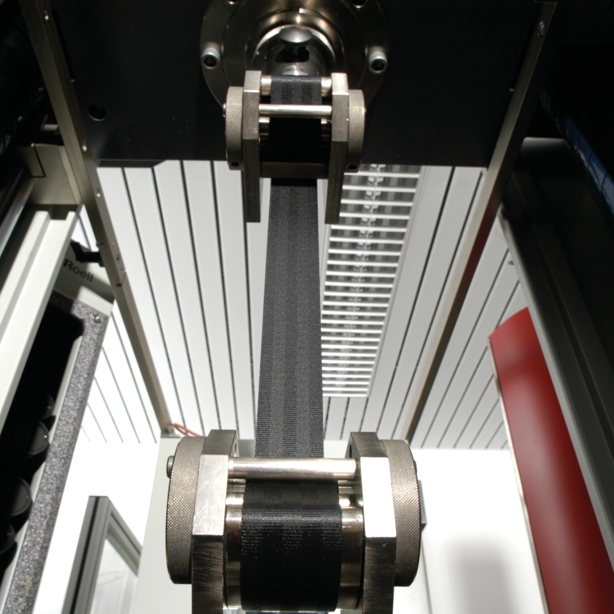
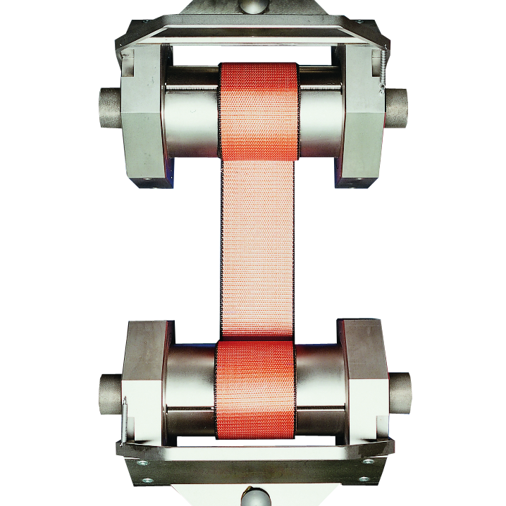
 | Roller grip | 2.5-250 kN | -70° … +250° | Straps and belts |
 | Capstan grip | 0.5-20 kN | +10° … 35° | Flat specimens, belts, tapes, yarn, tire cord, wire, continuous and spun fibers, low count yarns, twisted yarns, multifilaments, metal strands, wire, steel strip cord |
ZwickRoell also offers various special specimen grips and accessories:


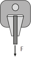
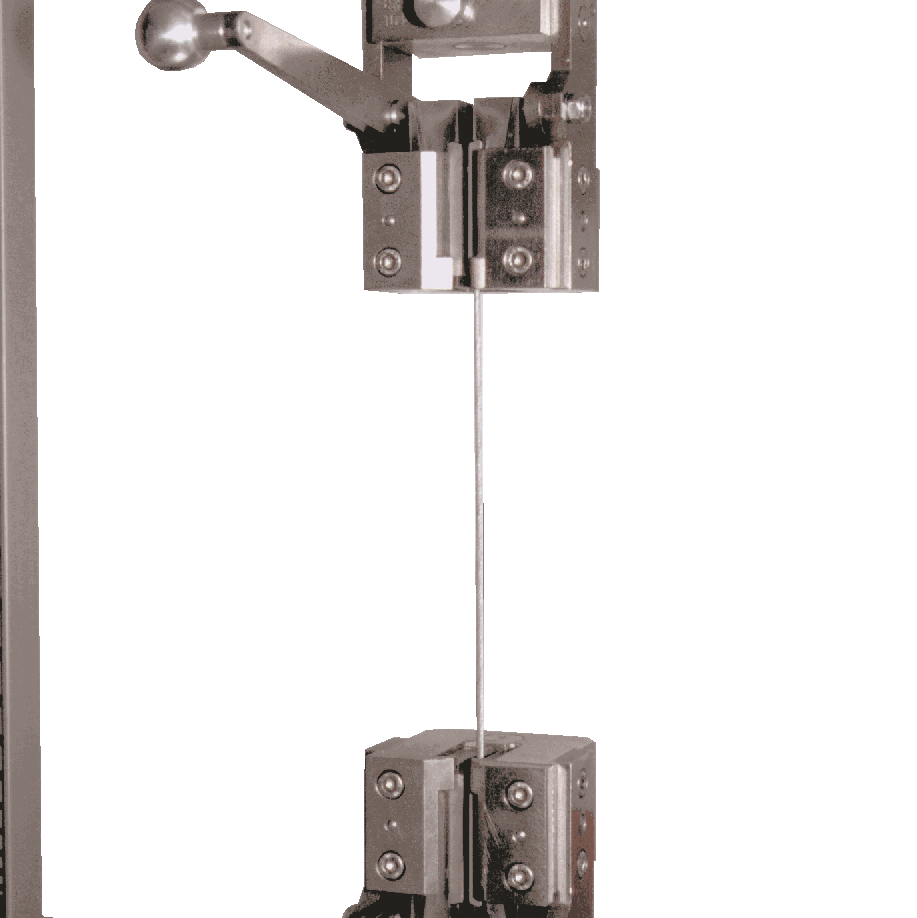
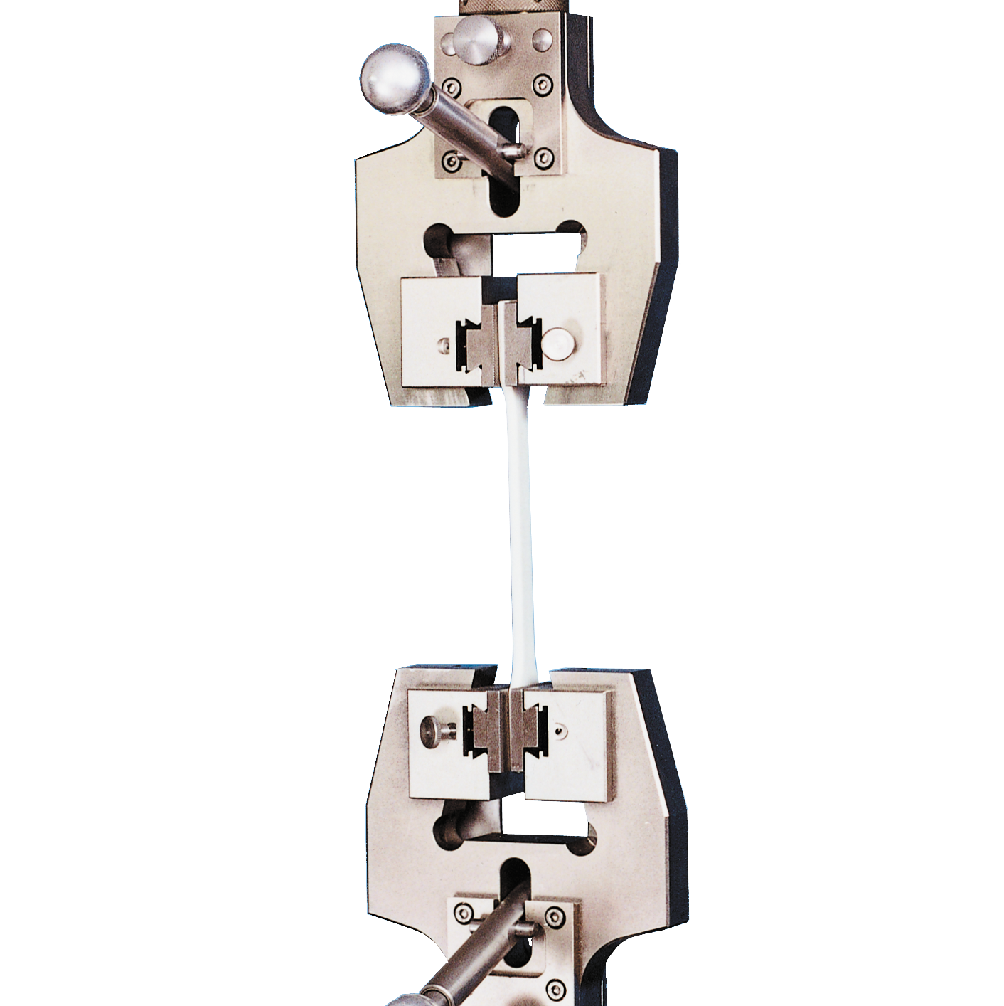
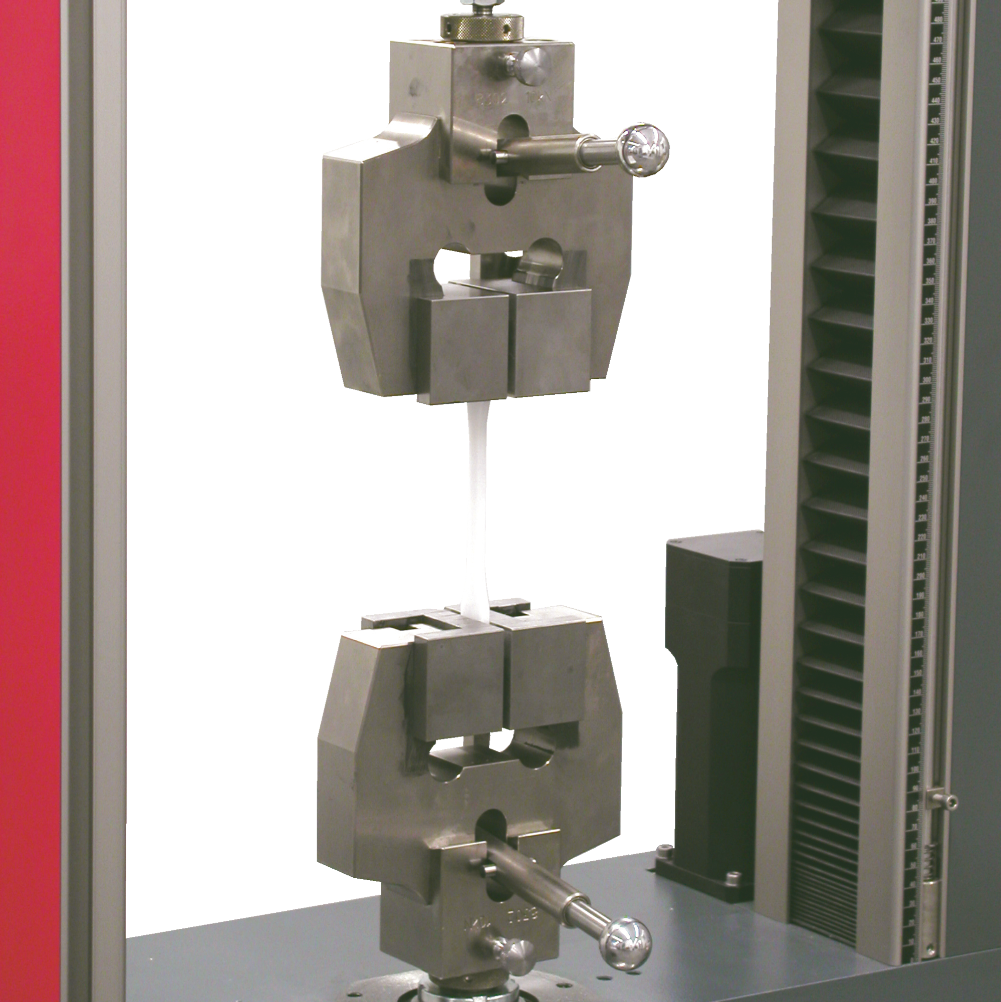
Screw grips
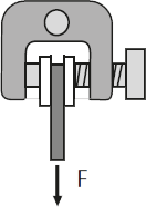
The screw grip is a single actuator specimen grip. A lead screw is used to open and close the grips, as well as apply gripping force before the test. On screw grips the gripping force is applied manually or via an electric motor. They can be used for smaller and larger test loads (from 20 N to 50 kN) and thin samples such as fine wires, fibers and foils.
The maximum opening width is 31 mm (varies based on jaw insert). The standard application range extends to test temperatures between -70 °C and +250 °C. The clamping force depends on the screw torque and the flexibility of the specimen grip.
Advantages & features of the screw grip:
- Simple and fast testing of joined (asymmetrical) specimens through adjustability of the opposing jaw.
- The measuring range of the force transducer can be widely utilized due to the lightweight design of the specimen grips.
- If the test configuration changes, the jaws can be changed quickly and easily without tools. The jaws are then automatically centered.
- Ball bearings ensure that the specimen is held securely even at low operating forces.
- The large opening width enables flexibility in use.
- Secure hold of the specimen is guaranteed even with changing applications. With the large selection of jaws, the specimen holder can be optimally adapted to your application.
- Even specimens prone to shrinkage are held securely by automatic retightening using a disc spring stack.
- The specimen grip can be easily operated in the temperature chamber and quickly reaches its test temperature due to its low mass.
- Accurate test results with a high cycle rate that is made possible through central insertion of the specimen with the aid of an easily adjustable centering stop.
- Fast and easy insertion and gripping of the specimen is achieved through the ergonomic and open design.
Screw grip downloads
- Product Information: Screw Grips, Fmax 20 N PDF 825 KB
- Product Information: Screw Grips, Fmax 200 N PDF 132 KB
- Product Information: Screw Grips, Fmax 200 N PDF 995 KB
- Product Information: Screw Grips, Fmax 500 N PDF 147 KB
- Product Information: Screw Grips, Fmax 1 kN PDF 493 KB
- Product Information: Screw Grips, Fmax 2.5 kN PDF 2 MB
- Product Information: Screw Grips, Fmax 5 kN/10 kN PDF 485 KB
- Product Information: Specimen grips for insulating material, Fmax 10 kN PDF 860 KB
- Product Information: Screw Grips, Fmax 20 kN PDF 208 KB
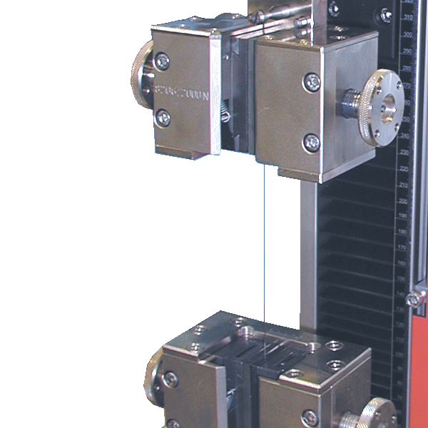
Spring loaded grips
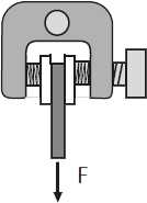
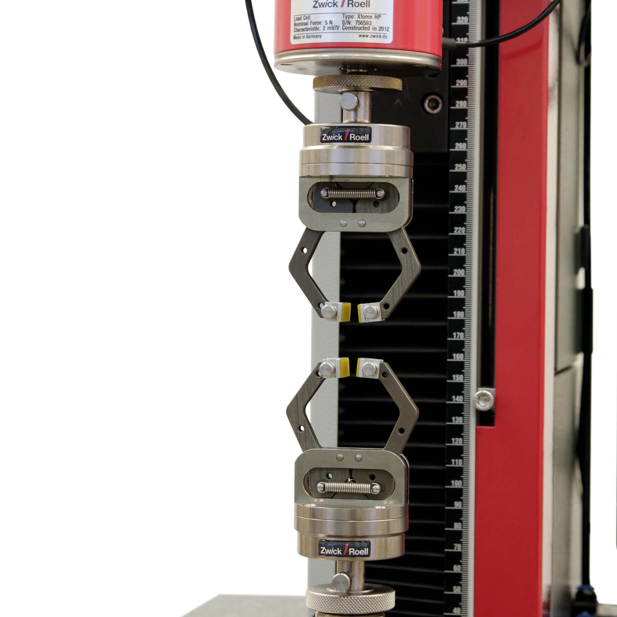
The spring loaded grip is ideal for tests with very small forces (Fmax 20 N to 50 N). Their weight is sufficiently low in relation to the nominal force of the attached load cell as to impose no restrictions on the force measurement range of the load cell. The gripping force is generated by a spring. The spring force can be preset, allowing clamping-sensitive materials to always be tested using the same gripping force.
Advantages and features of the spring loaded grip
- Precise test results with a high number of cycles that is achieved with the centering aid for inserting wires and threads
- With the constant gripping force repeatable test results can be attained.
- Fast and easy insertion of the specimen is achieved through the ergonomic and open design
- The jaws can be tilted and precisely adjusted to the specimen
- With the lightweight construction of the specimen grip, the measurement range of the load cell can be optimally utilized.
- If the application changes, the jaws can be changed quickly and easily without tools. The jaws are then automatically centered (only for Fmax 20 N)

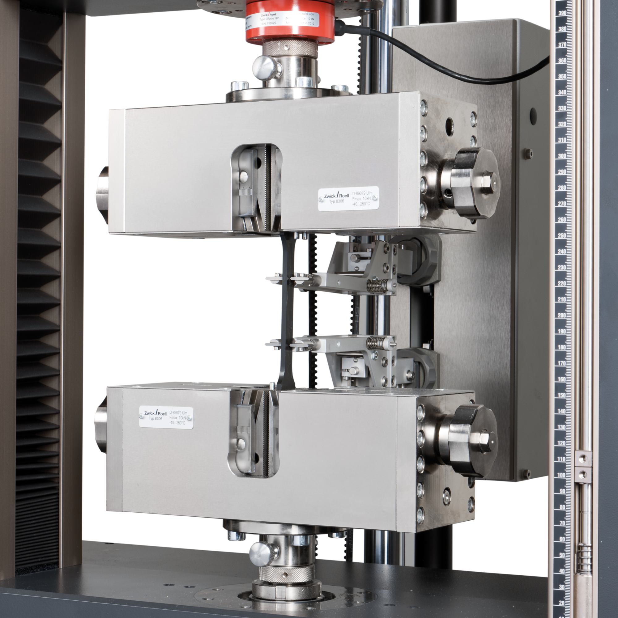
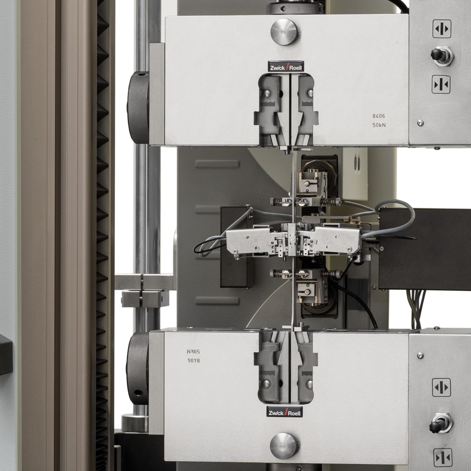
Pneumatic grips
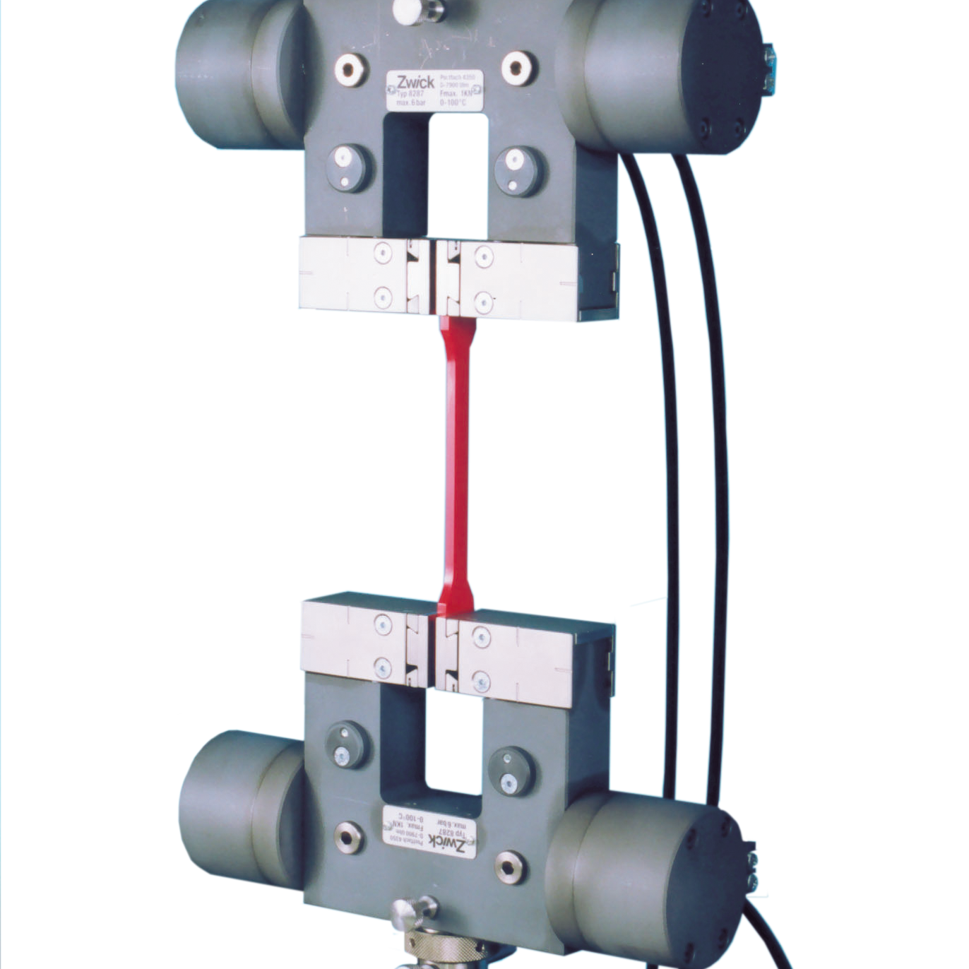
Pneumatic grips are particularly useful when a variety of materials, especially those sensitive to clamping forces, must be gripped with minimum amount of changeover. The gripping force is generated by pneumatic actuators acting on the jaws directly or via a lever system.
Features that apply to all pneumatic grips:
- The separation of tensile and gripping forces ensures a constant gripping force over the course of the entire test sequence. For specimens prone to shrinkage, the gripping force is uniformly maintained by constant pneumatic pressure.
- The contact force on the specimen is reproducible.
- Gripping-sensitive specimens can be held securely by adjusting the pneumatic pressure, avoiding jaw breaks.
- The tensile load can be applied statically or by pulsating. Depending on the type, they can also be used for compression and alternating load tests.
- The primary stress is the tensile load and it can be static or pulsating. Depending on the type, you may also be able to use them for compression and alternating load tests.
- Depending on the design principle, the gripping area is freely accessible.
- The larger grips can remain in place while small load cells, specimen grips, test fixtures and test devices are attached without having to dismantle the specimen grips—a great time saver.
- There is a wide variety of jaws available, based on material, surface, and size of the clamping surface.
- Pneumatic grips offer a more economical alternative when compared to hydraulic grips.
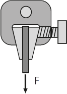
Single actuator pneumatic grips
Single actuator pneumatic grips can be used for symmetrical and asymmetrical gripping of specimens (for example, for shear tests). Opening and closing as well as applying the gripping force before the test occurs pneumatically via a toggle valve on the specimen grip. It is not possible to change the compression force at the specimen grips. There is no need for an additional pneumatic control unit, however it can be added as an option. The opposing jaw can be steplessly adjusted. They are intended for a test load of 20 N to 30 kN.
Advantages of the single actuator pneumatic grip
- Even shrinking specimens are held securely by the constant pneumatic pressure.
- The constant gripping force helps you attain repeatable test results.
- High specimen throughput thanks to fast insertion and precise centering of the specimen using the insertion aid and guide groove.
- Simple and quick specimen change thanks to the operation of the specimen holders by means of a toggle lever.
- Simple and fast testing of joined (asymmetrical) specimens through adjustability of the opposing jaw
- Fast and easy insertion and gripping of the specimen is achieved through the ergonomic and open design.
- Special connection device for use in the temperature chamber with integrated compressed air supply. A receptacle for condensation water serves as a drainage system to remove condensation from the test area. The opposing jaw can be adjusted steplessly or set-by-step.
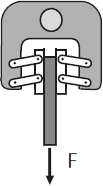
Double actuator pneumatic grips
The double actuator pneumatic grip always closes symmetrically with respect to the tensile axis, thereby eliminating the need for thickness adjustment. The jaws are secured with a threaded pin. They can be replaced without tools. An additional pneumatic control unit is not necessary. The jaws are gently opened and closed via a toggle valve. This offers advantages in terms of zero-force control. The pneumatic clamping pressure on the specimen grip cannot be changed. This is only possible with an additional pressure relief valve.
Advantages of the double actuator pneumatic grip
- The symmetrically closing jaws save time required for adjusting to varying specimen thicknesses and ensure that the specimen is held exactly in the test axis.
- If the application changes, the jaws can be changed quickly and easily without tools. The jaws are then automatically centered.
- The constant gripping force helps you attain repeatable test results.
- Even shrinking specimens are held securely by the constant pneumatic pressure.
- Simple and quick specimen change thanks to the operation of the specimen holders by means of a toggle lever.
- Fast and easy insertion and gripping of the specimen is achieved through the ergonomic and open design.
- The clamping force is always constant, regardless of the test force, making it ideal for materials that are sensitive to clamping or when high specimen throughput is required.
- Always closes symmetrically in relation to the tensile axis. This means the specimen is gripped in a precise axial position, making it unnecessary to set the specimen thickness.
Body over wedge pneumatic grips
With the pneumatic specimen grip, emphasis is on fast, reproducible and, most importantly, parallel gripping. The full clamping force is available right from the start, so that the stationary jaws transfer the test speed directly to the specimen. With pneumatic grips from the body over wedge portfolio, the position of the jaws remains constant in the test direction as the specimen is gripped. This means that the grip-to-grip separation does not depend on the specimen thickness.
Simple extensions are used in combination with temperature chambers The pneumatic actuator is positioned outside the chamber.
Advantages of body over wedge pneumatic grips:
- Whether you are testing sensitive specimens or specimens with short clamping lengths, these symmetrically designed grips guarantee optimum clamping.
- When determining the exact nominal strain the grip-to-grip separation does not depend on specimen diameter. Setup time is minimized.
- Reduced weight plus a compact design simplify handling, ensure short heating and cooling times in the temperature chamber. and enable long travel.
- Absolutely secure gripping right from the start of the test for specimens prone to light slippage.

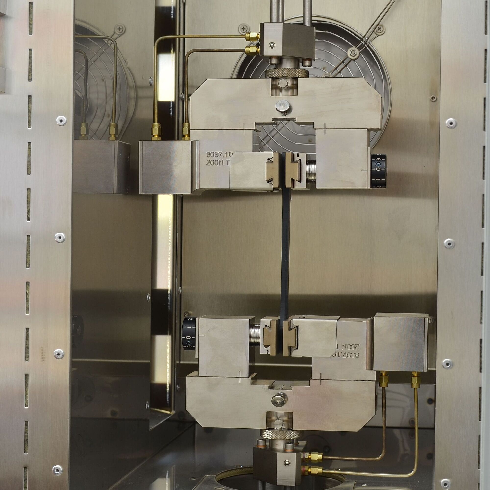
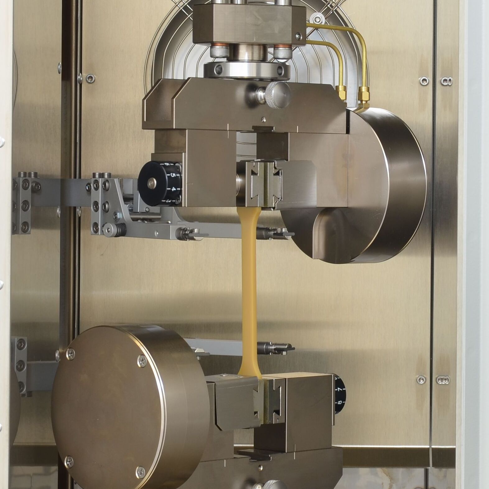
Pneumatic grips for the temperature chamber
These pneumatic grips are specifically designed for use in temperature chambers. They have a special connection device for use in the temperature chamber with integrated compressed air supply. A receptacle for condensation water serves as a drainage system to remove condensation from the test area. The opposing jaw can be adjusted steplessly or set-by-step.
The height of the connection device depends on the test system used, the temperature chamber and the specimen-related stroke ratios in the temperature chamber. It is therefore determined on an order-related basis.
Pneumatic control unit
The pneumatic control unit offers safe operation in accordance with all standards and flexible operating options:
- Push-button operation directly on the control unit
- Control via foot pedal unit
- Ergonomic remote control with display
- Connection to our testXpert testing software
The pneumatic control unit can be combined with all versions of pneumatic grips and load frames included in the ZwickRoell series portfolio. It is suitable for specimens that are not dimensionally stable, are sensitive to clamping and slip easily—even with shrinking specimen thickness. It is also ideal for high specimen throughput and frequently changing specimen materials.

Downloads pneumatic grips
- Product Information: Pneumatic Grips, Fmax 50 N/200 N PDF 511 KB
- Product Information: Pneumatic Grips, Fmax 200 N PDF 485 KB
- Product Information: Pneumatic Grips, Fmax 500 N PDF 726 KB
- Product Information: Pneumatic Grips, Fmax 1 kN, Integrated Control Valve PDF 326 KB
- Product Information: Pneumatic Grips, Fmax 1 kN PDF 3 MB
- Product Information: Pneumatic Grips, Fmax 2.5 kN PDF 3 MB
- Product Information: Pneumatic grips, Fmax 5 kN/10 kN/30 kN PDF 387 KB
- Product Information: Pneumatic Grips, Fmax 20 N PDF 596 KB
- Product information: Pneumatic grips, Fmax 200 N/1 kN PDF 1 MB
- Product Information: Pneumatic Grips, Fmax 2.5 kN PDF 557 KB
- Product Information: Pneumatic Grips, Fmax 10 kN/20 kN PDF 805 KB
- Product Information: Pneumatic Grips, Fmax 50 kN/100 kN PDF 661 KB
- Product Information: Pneumatic Body Over Wedge Grips Fmax 10 kN/20 kN PDF 2 MB
- Product Information: Pneumatic Grips for Temperature Chambers, Fmax 200 N/2.5 kN PDF 257 KB
- Product Information: Pneumatic Grips for Temperature Chambers, Fmax 1 kN PDF 604 KB
- Product Information: Pneumatic Grips for Temperature Chambers, Fmax 10 kN/20 kN PDF 3 MB
- Product Information: Pneumatic Control Unit PDF 225 KB

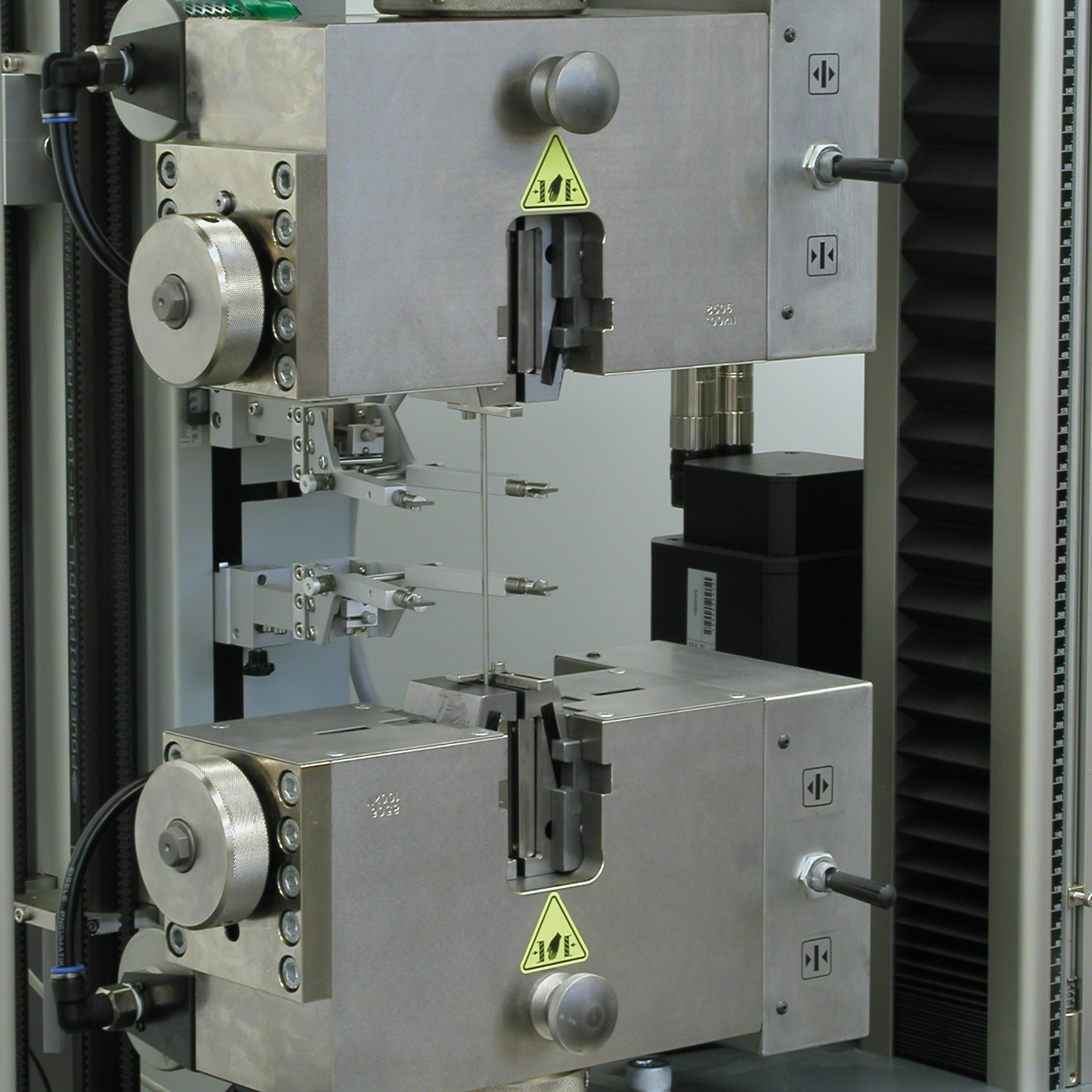
Hydraulic grips
Hydraulic grips are primarily used when test forces of 50 kN or more and high gripping forces are required (Fmax of 10 kN to 2,000 kN possible). The contact pressure is accurately reproducible.
Operating principle of hydraulic grips
The oil pressure is set at the hydraulic power pack according to the required closing pressure for the specimen grips. The control unit controls the closing and opening procedure separately for the top and bottom specimen grips.
Furthermore, the closing procedure is divided into a closing phase and gripping phase when a a universal hydraulic power pack is used. In the closing phase, the specimen is initially held on the upper end for safety reasons. During gripping, the full gripping force is applied. The force value is based on the expected tensile force.
Double-sided actuators
All hydraulic grips are equipped with double-sided actuators. This means the specimen grip opens hydraulically and not by means of spring return mechanism. The closing and opening pressure can be adjusted.
In contrast to single-acting actuators that open by means of a spring return mechanism, double-sided actuators ensure that the specimen grips always open safely . This also applies if the specimen is crooked or jammed. Additionally, the full opening stroke is not necessary because the opening procedure can be interrupted at any point using the Stop button. The opening stroke can be adjusted according to thickness. Especially with thin specimens, the test time is reduced and the risk of pinching parts of the body is minimized.


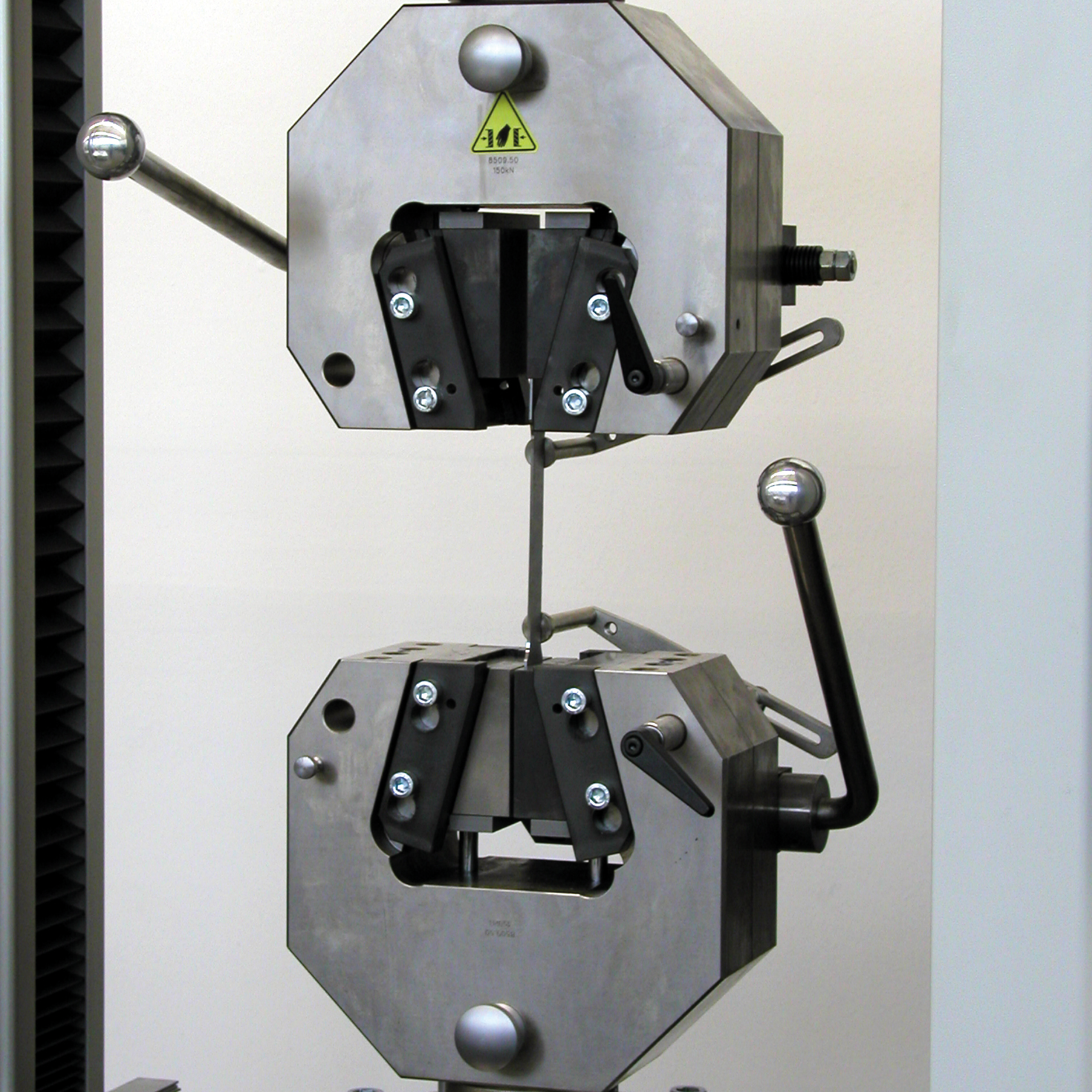
Single actuator hydraulic grips
Single actuator hydraulic grips can be used for symmetrical and asymmetrical gripping of specimens (for example, for shear tests). The thickness of the specimen is adjusted using a spindle unit.
The single-actuator hydraulic grips are also available with a tandem cylinder to enable uniform force application to the specimen (especially suitable for tests on fabrics, textiles and geotextiles).
Advantages and features of single actuator hydraulic grips
- Hydraulic grips have an eccentric piston shape with a long piston stroke, achieving a deep clamping surface position and a large opening width.
- The alignment of the jaws, specimen grips, and piston facilitates gripping of short specimens as well.
- Defined force application ensures optimum gripping of sensitive materials.
- Exactly reproducible contact force.
- Specimen grips can be installed in testing systems at three different angle settings (0°, 45°, and 90°).
- T-slots in the lower part of the basic body serve as a mounting for the T-slot system, enabling the accommodation of smaller load cells, specimen grips, test tools, and fixtures (except hydraulic grips, type 8392, Fmax 10 kN).
- Prismatic jaws (jaws with V-slots) can be rotated and have two-fold use: For round and flat specimens or for round specimens with various diameters (jaws with crosswise arranged V-slots)
- The upper and lower grips can be opened and closed either individually or together via remote control or PC.
- The ratio between gripping and tensile forces can be adjusted individually, ensuring that the specimen is held securely (at maximum tensile force approximately double gripping force is required).
- Hydraulic grips are designed to offer optimal specimen feeding.
- An adjustable, scaled stop ensures precise vertical specimen gripping for manual special feeding.
- For easier specimen centering, a centering stop can be used.
- For safety reasons, specimen tongs can be used to insert the specimen.

Single actuator hydraulic grips for geotextiles
Double actuator hydraulic grips
Double actuator hydraulic grips always close symmetrically with respect to the tensile axis. This means the specimen is gripped in a precise axial position, thereby eliminating the need for thickness adjustment.
- The constant gripping force allows for repeatable test results.
- Reliable test results are guaranteed with the optimal interaction between the hydraulic power pack, the electronics, and the testing software. The force-zero control prevents unwanted forces on the specimen during the gripping process.
- Time is saved due to quick and easy adaptation of small specimen grips and test fixtures to large specimen grips via the T-slotted system. Precise alignment ensures reliable test results.
- The symmetrically closing jaws save time required for adjusting to varying specimen thicknesses and ensure that the specimen is held exactly in the test axis.
- Short specimen can also be gripped due to the special design of the specimen grip.
- Fast and easy insertion of the specimen is achieved through the ergonomic and open design
- An adjustable centering stop ensures precise test results, even with high specimen throughput rates.

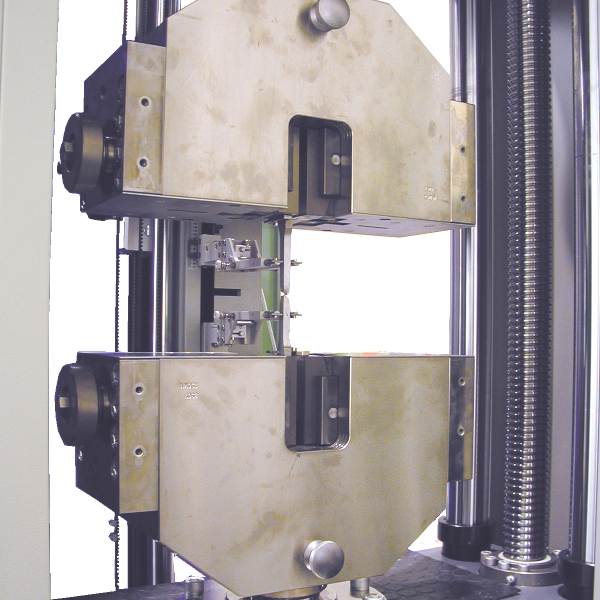
Body over wedge hydraulic grips
The body over wedge hydraulic grip is double acting and used for symmetrical gripping. Positively driven jaws enable reproducible gripping of the specimen. The symmetrical design and high degree of stiffness of the main body of the grips make them ideal for tests in which strict requirements are placed on the alignment of the specimen to the test axis.
The specimen grips are symmetrically closing wedge grips, which are opened and closed hydraulically. Only the outer casing is moved vertically via the hydraulics. The movement of the housing causes the wedge jaws to be pushed parallel to one another in a horizontal plane.
Advantages of body over wedge hydraulic grips
- The constant gripping force allows for repeatable test results.
- Reliable test results are guaranteed with the optimal interaction between the hydraulic power pack, the electronics, and the testing software. The force-zero control prevents unwanted forces on the specimen during the gripping process.
- The specimen grip is suitable for alignment-critical applications, such as specimens sensitive to transverse tensile forces.
- With the parallel gripping operation (no differential movement of the jaws) the test speed is transfered directly to the specimen.
- Fast and easy insertion of the specimen is achieved through the ergonomic and open design
- An adjustable centering stop ensures precise test results, even with high specimen throughput rates.
- When testing composite specimens for example, the specimen grip offers advantages due to easy cleaning.
- The body over wedge hydraulic grips are also suitable for servohydraulic testing machines and are characterized by their ease of use. When used with servohydraulic testing machines they are connected to the existing pressurized oil supply. A small power pack is required for use in static materials testing machines.

Hydraulic Power Pack - GripControl
Gentle gripping with GripControl hydraulic power packs
- The GripControl hydraulic power packs are tailor-made for ZwickRoell hydraulic grips and tools/fixtures up to 250 kN.
- All power packs feature a high degree of safety, including Emergency STOP chain and inching mode.
- Space-saving design enables the power pack to fit under the table. Extremely high availability, maintenance-friendly design, and long service life are stand-out features of these power packs.

Downloads hydraulic grips
- Product Information: Hydraulic Grips, Fmax 50 kN PDF 425 KB
- Product Information: Hydraulic Grips, Fmax 100 kN/250 kN PDF 638 KB
- Product Information: Hydraulic Grips with Large Opening, Fmax 10 kN PDF 604 KB
- Product Information: Hydraulic Specimen Grips for Geotextiles, Fmax 50 kN/100 kN/250 kN PDF 525 KB
- Product Information: Hydraulic Grips for Short Clamping Lengths, Fmax 50 kN/70 kN PDF 376 KB
- Product Information: Hydraulic Grips for Short Clamping Lengths, Fmax 150 kN/250 kN PDF 327 KB
- Product Information: Hydraulic Grips up to 2500 kN PDF 280 KB
- Product Information: Hydraulic Body Over Wedge Grips, Fmax 100 kN PDF 608 KB
- Product Information: Hydraulic Body Over Wedge Grips, Fmax 250 kN PDF 834 KB
- Product Information: Hydraulic Wedge Grips, 25 kN, for Servohydraulics PDF 360 KB
- Product Information: Hydraulic Wedge Grips, 100 kN, for Servohydraulics PDF 616 KB
- Product Information: Hydraulic Wedge Grips, 250 kN, for Servohydraulics PDF 349 KB
- Product Information: GripControl Hydraulic Power Pack PDF 369 KB
- Product Information: Universal Hydraulic Power Pack PDF 288 KB
Wedge grips
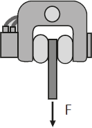
Wedge grips are symmetrically closing specimen grips. They consist of a solid base body with exchangeable jaw inserts or fixed jaws, as well as an operating unit for opening and closing the sample holder. A lever is used to open and close the grips, as well as apply gripping force before the test. They offer a freely accessible clamping area.
A distinction is made between two operating principles:
- Body over wedge (also BoW)
- Lever

Downloads wedge grips
- Product Information: Wedge Grips, Fmax 2,5 kN/5 kN PDF 161 KB
- Product Information: Wedge Grips, Fmax 10 kN/20 kN PDF 713 KB
- Product Information: Wedge Grips, Fmax 10 kN/50 kN PDF 230 KB
- Product Information: Wedge Grips “Body Over Wedge”, Fmax 10 kN PDF 690 KB
- Product Information: Wedge grips, Fmax 30 kN / 50 kN PDF 295 KB
- Product Information: Wedge Grips “Body Over Wedge”, Fmax 50 kN PDF 427 KB
- Product Information: Wedge grips, Fmax 100 kN PDF 349 KB
- Product Information: Wedge Grips “Body Over Wedge”, Fmax 100 kN PDF 451 KB
- Product Information: Wedge grips, Fmax 150 kN PDF 259 KB
- Product Information: Wedge Grips “Body Over Wedge”, Fmax 250 kN PDF 444 KB
Wedge screw grips
Wedge screw grips combine the mechanical properties of screw grips and wedge grips. Thickness is adjusted and a preload force is generated via a screw action, which helps prevent specimen slipping at the beginning of the test.
Features of wedge screw grips:
- The main gripping force is generated by the wedge action.
- The gripping force is proportional to the actual tensile force (self-clamping), ensuring secure gripping of a wide range of materials.
- Large grip-to-grip separation allows the surface pressure to be kept low, avoiding jaw breaks.
- Without removing the specimen grips, small load cells, specimen grips, tools and test fixtures can be adapted to the large specimen grips (from Fmax 50 kN) in a time-saving manner using the optional mounting unit
- Easy replacement of jaw inserts without the need to use tools
- Wedge screw grips with Fmax 50 kN and above can be operated via a pneumatic motor, These specimen grips are opened and closed by a pneumatic motor; the actuating unit is located directly on the specimen grip
- Low overall height.
- pneumatic motor; the pneumatic actuator is located directly on the specimen grip
- Strain rate control in accordance with standards DIN EN ISO 6892-1:2009 and ASTM E8 – 09.
Highlight:
Switchable synchronization allows wedge screw grips (Fmax 10 kN and above) to grip both symmetrically and asymmetrically. The asymmetry level is easily adjustable and is maintained reliably, even with regripping. One-handed operation is possible with either hand, including with asymmetrical specimens, ensuring that the specimen attachment point is always in the test axis.


Downloads wedge screw grips
- Product Information: Wedge screw grips, Fmax 500 N / 2,5 kN PDF 530 KB
- Product Information: Wedge Screw Grips, Fmax 10 kN PDF 396 KB
- Product Information: Wedge Screw Grips, Fmax 10 kN/30 kN PDF 681 KB
- Product Information: Wedge Screw Grips Manual, Fmax 50 kN/100 kN/150 kN PDF 580 KB
- Product Information: Wedge Screw Grips Manual, Fmax 250 kN PDF 161 KB
- Product Information: Wedge Screw Grips Motorized, Fmax 250 kN PDF 535 KB
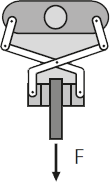
Pincer grips
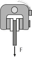
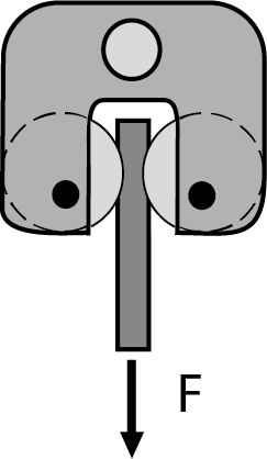
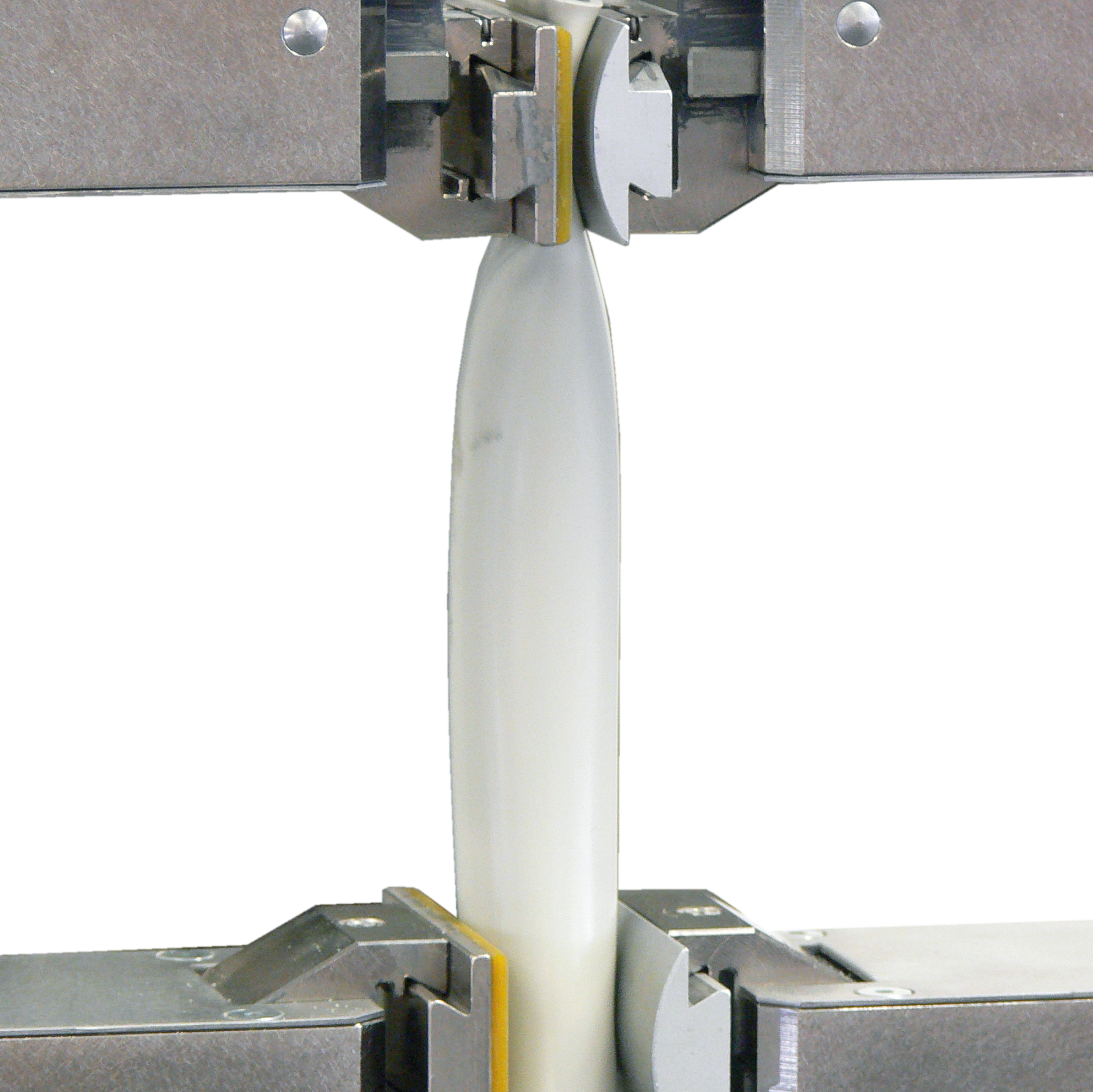
The pincer grip is a double actuator specimen grip. The grip is opened and closed via a clamping lever. The prestressed spring holds the specimen grip open for specimen insertion. If the specimen grip is closed, the prestressed spring generates the required gripping force. The gripping force is increased proportionally by the pincer principle as the tensile force increases. This ensures automatic retightening for specimens prone to shrinkage.
Pincer grips are primarily used to test highly ductile plastics and elastomers. The pincer principle produces a strong increase in gripping force during the test.
Advantages and features of pincer grips:
- The gripping force is proportional to the tensile force (self-tensioning)
- Due to the lateral movement of the pincer grips, the specimens are always loaded centrally to the tensile axis
- Fast and easy insertion of the specimen is achieved through the ergonomic and open design
- Due to their high temperature resistance and low height, the pincer grips are very well suited for use in temperature chambers. They are easy to operate and quickly reach the test temperature due to their low mass

Downloads pincer grips
- Product Information: Wedge Screw Grips, Fmax 500 N/2.5 kN PDF 530 KB
- Product Information: Wedge Screw Grips, Fmax 10 kN PDF 396 KB
- Product Information: Wedge Screw Grips, Fmax 10 kN/30 kN PDF 681 KB
- Product Information: Wedge Screw Grips Manual, Fmax 50 kN/100 kN/150 kN PDF 580 KB
- Product Information: Wedge Screw Grips Manual, Fmax 250 kN PDF 161 KB
- Product Information: Wedge Screw Grips Motorized, Fmax 250 kN PDF 535 KB
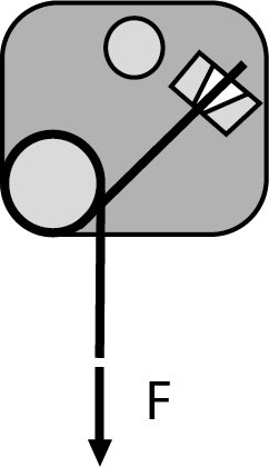
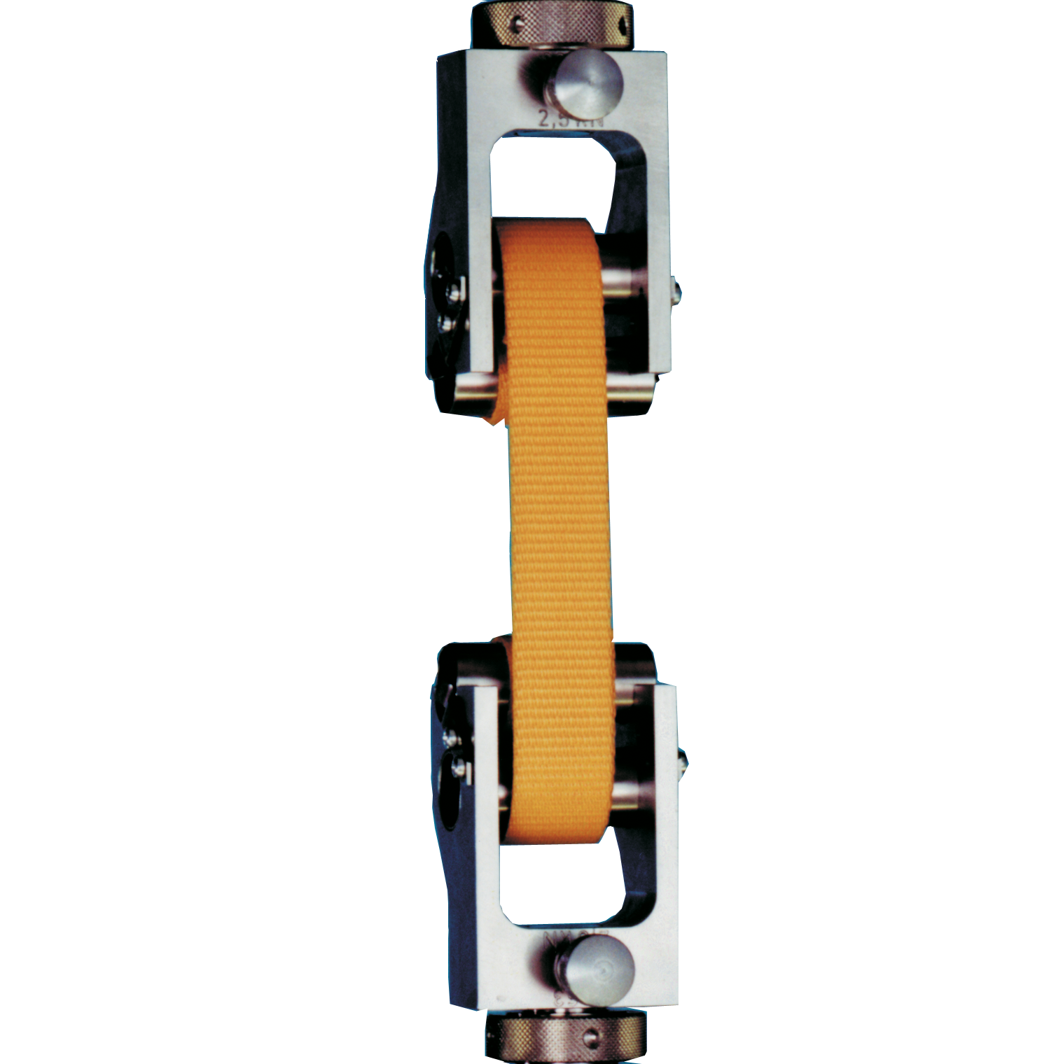
Toggle grips
Toggle grips are self-clamping specimen grips. Gripping occurs through action of the toggle lever. The specimen is inserted by lifting the toggle lever. The sample can either be placed around the toggle lever or clamped without deflection. Toggle grips are particularly suited for plastics in almost any temperature environment.
Features of toggle grips:
- Due to the low height and a temperature range of -15 ... +80 °C, the specimen grip is also suitable for use in temperature chambers
- The design ensures quick and easy gripping of the specimen

Grips with deflection (capstan grips)
A force reduction curve is used for specimen grips with deflection. The force in the specimen is reduced over the course of the load reduction curve. The required gripping forces can be reduced in the pneumatic control unit. The maximum test load ranges from 500 N to 20 kN
Advantages of capstan grips:
- With pneumatic end clamping, the clamping force remains constant and supports high specimen throughput
- Automatic centering of the specimen via guide grooves in the load reduction curve
- Due to the symmetrical weight distribution, the center of gravity of the specimen grips is close to the tensile axis
- No transverse forces are transmitted to the load cell via the specimen grips.
")

Capstan grip versions
The pneumatic grip with deflection is available in different versions:
- 360° Capstan Grip
- 90° Capstan Grip
- 180° Capstan Grip
- 270° Capstan Grip
These pneumatic grips with deflection are single actuator specimen grips for clamping filamentary tensile specimens. The force reduction curve with deflection carefully reduces the tensile force on the clamping position. Pneumatic clamping ensures a constant gripping force and can be easily and reproducible set. The specimen is held securely, jaw breaks are avoided.
These capstan grips are used for yarn, tire cord, high-tenacity plastic yarns or steel strip cords.
Advantages & features of the capstan grip
- Reliable test results thanks to secure specimen retention even with shrinking specimens
- High specimen throughput due to quick insertion and precise centering of the specimen by means of a guide groove
- If the application changes, the jaws can be changed quickly and easily without tools. The jaws are then automatically centered.
- Simple and quick specimen change with two hands by operating the specimen grips via the foot control unit (at 180° and 270°)
- The specimen grip can be optimally adapted to different specimen materials by means of interchangeable force reduction curves (at 90° and 180°)
- The symmetrical weight distribution of the specimen grip ensures precise force measurement (at 180° and 270°)
- In addition, the specimen grip can also be used vertically without force reduction curves (at 90°)
- Two specimen grips in one. Depending on the specimens, the specimen grips can be used with the load reduction curve as well as without it. This ensures optimum clamping even with changing specimens (at 90°)
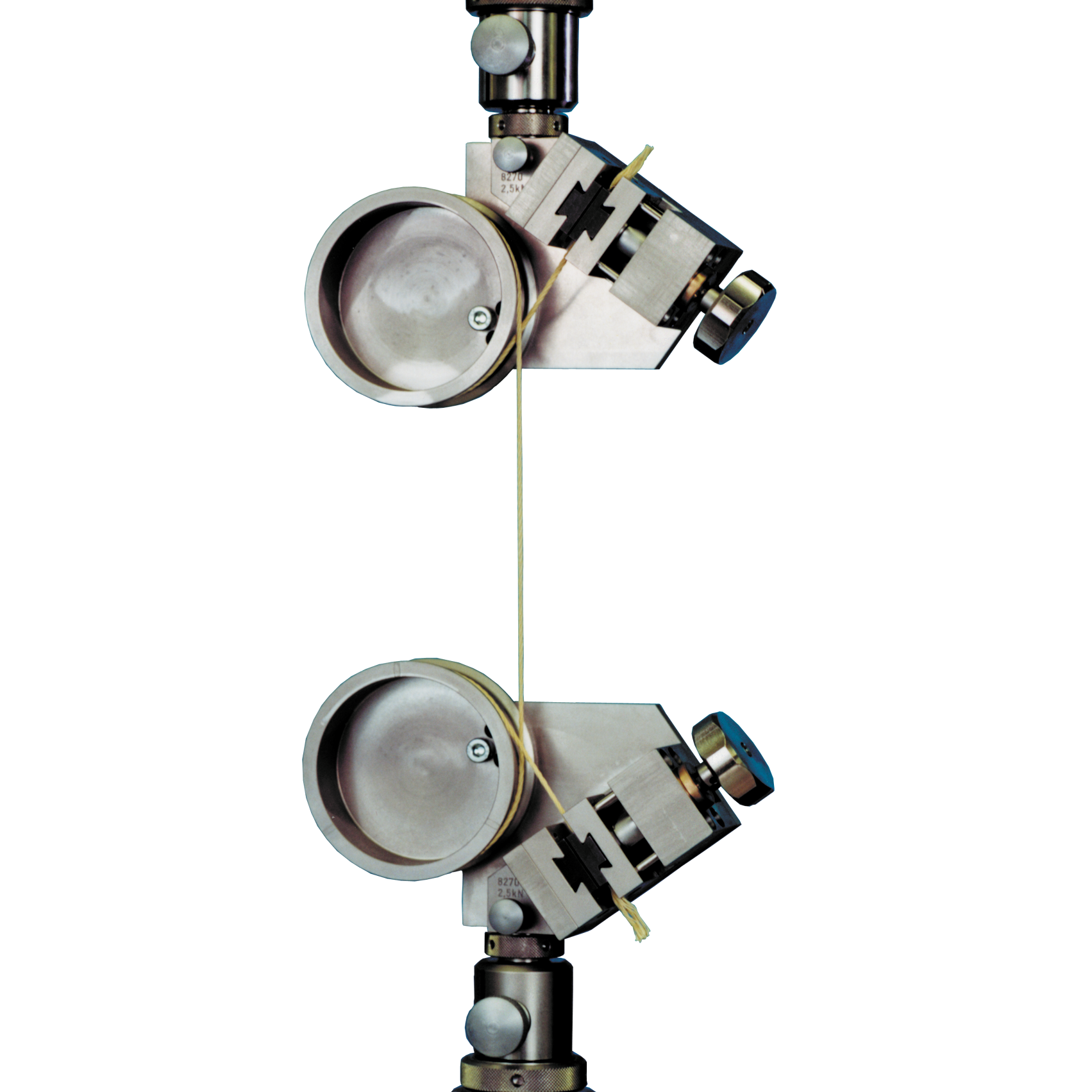
Double capstan grips
The double capstan grip can be used to grip filamentary, high-extension tensile specimens. With this deflection principle a force differential occurs over two stages, allowing specimen failure within the gauge length with no jaw breaks. After the deflection of the double thread, a prestress weight (not included in scope of delivery) is attached. During this phase all three rollers are moving in order to balance the extensions which are created by the attachment of the pretension weight. The three lengths are adjusted to the material being tested. Finally, the double thread is clamped in the height-adjustable specimen grip.
After the specimen grip closes the deflection rollers are locked, This results in frictional forces between the rollers and the specimen, which gently reduce the tensile force prior to end clamping (specimen grip), ensuring that the specimen is gripped securely and prevents the jaws from breaking. A specimen grip with constant gripping force is used to clamp the double thread because the specimen to be tested can frequently slip out from between the gripping areas.
The double capstan grip is mainly used for materials such as rubber threads and elastofibers
Advantages of the double capstan grip:
- Wrapping the specimen around the load reduction rollers ensures gentle gripping without jaw breaks.
- The specimen grip ensures precise strain measurements on highly extensible threads
- Avoiding clamping breaks additionally saves time spent on testing

Downloads capstan grips
- Product Information: Capstan Grips Fmax 10 kN/20 kN PDF 407 KB
- Product Information: Pneumatic grips with 90° deflector, Fmax 1 kN PDF 219 KB
- Product Information: Specimen Grips for High-Strength Plastic Yarn, Fmax 1 kN PDF 364 KB
- Product Information: Specimen Grips for High-Strength Plastic Yarn, Fmax 2.5 kN PDF 549 KB
- Product Information: Special Grips for Yarn, Fmax 2.5 kN PDF 483 KB
- Product Information: Specimen Grips for Steel Tire Cord to BISFA, Fmax 10 kN PDF 339 KB
- Product Information: Double Capstan Grips, Fmax 500 N PDF 372 KB
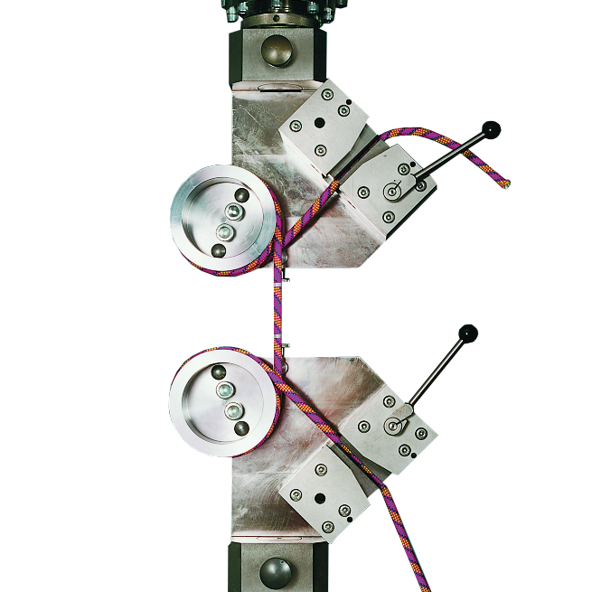
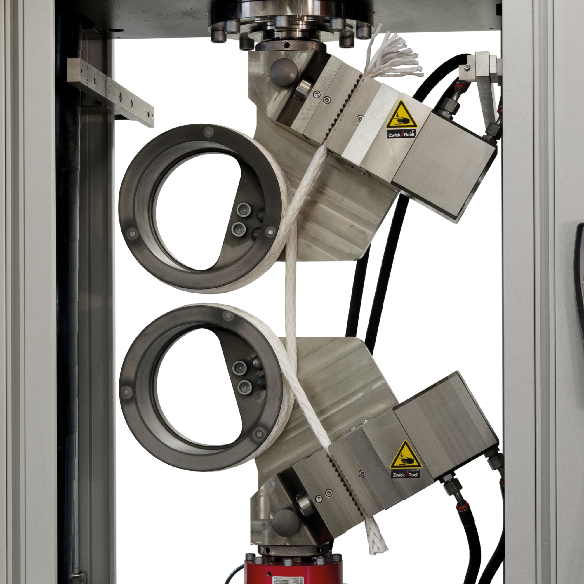
Specimen grips for ropes and yarns
Specimen grips for ropes and yarns can be used for testing tensile specimens that are not dimensionally stable.
Tensile stress on the specimen is reduced via frictional contact with the load reduction roller. The ends are clamped mechanically via a screw (with force amplification if required), a wedge, or a hydraulic gripping unit. The specimen is automatically centered by the load reduction roller's groove when wrapped.
The maximum test load ranges from 2.5 kN to 100 kN. The specimen grips can be used for rigid plastics and textiles, metallic materials, plastics and natural fibers, high-strength ropes and yarns.
Advantages of specimen grips for ropes and yarns:
- Wrapping the specimen around the load reduction rollers ensures gentle gripping without jaw breaks.
- Optimum adaptation to different specimen materials thanks to interchangeable load reduction rollers
- Different jaws and load reduction rollers are available for different specimen materials.
- If the application changes, the jaws can be changed quickly and easily without tools. The jaws are then automatically centered.


Downloads for rope grips
- Product Information: Rope Grips, Fmax 2,5 kN PDF 222 KB
- Product Information: Rope Grips, Fmax 2,5 kN PDF 160 KB
- Product Information: Rope Grips, Fmax 10 kN/50 kN PDF 240 KB
- Product Information: Rope Grips, Fmax 100 kN PDF 144 KB
- Product Information: Rope Grips, Fmax 100 kN PDF 569 KB
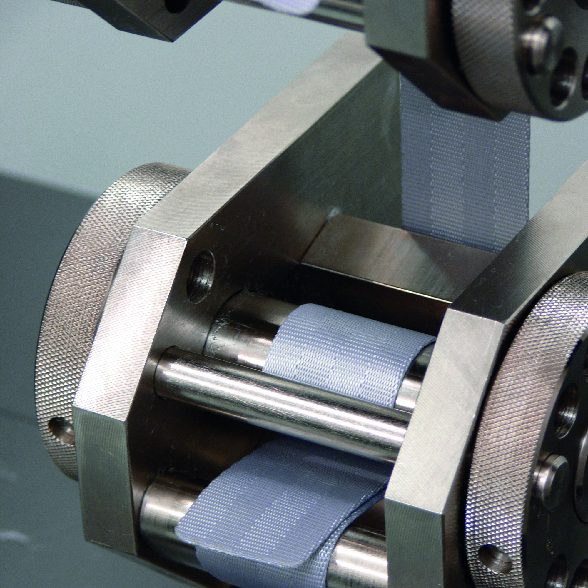
Roller grips
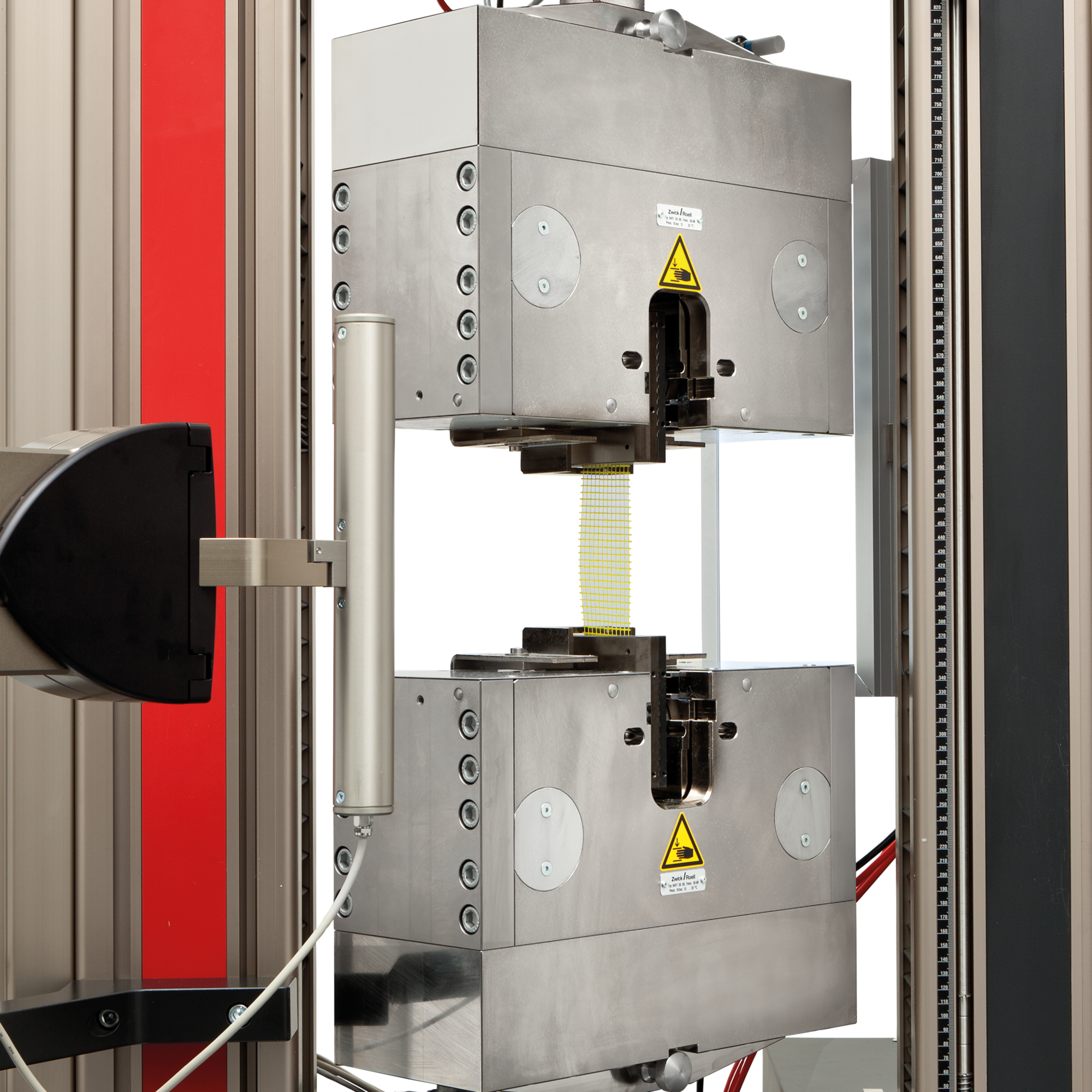
The roller grip is used for testing strip-shaped tensile specimens. The gripping force is generated through self-gripping by looping the specimen multiple times and applying tensile force. For precise strain measurement, optical extensometers are used.
Advantages of the roller grips
- The specimen grips are available with a maximum force measurement range of 2.5 kN to 250 kN
- Thanks to the ergonomic design, the specimen can be quickly and easily inserted into the clamping area (max. clamping width: 220 mm), which is freely accessible from the front
- The specimen grip is ideal for specimens that are sensitive to clamping
- and for tests in temperature chambers (temperature range: -70 ... +250 °C
- Due to the low height of the specimen grips, specimens with a large elongation can be tested

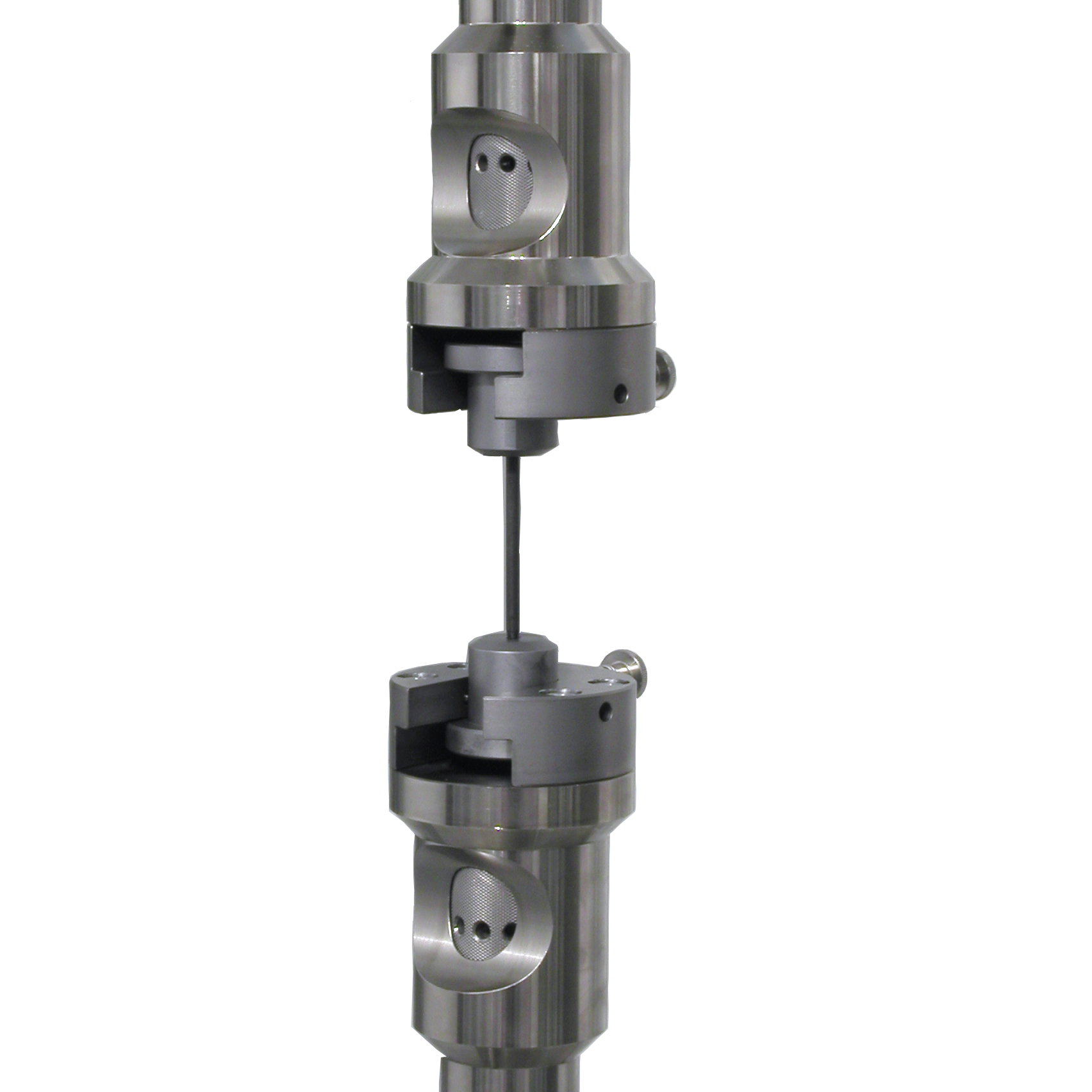
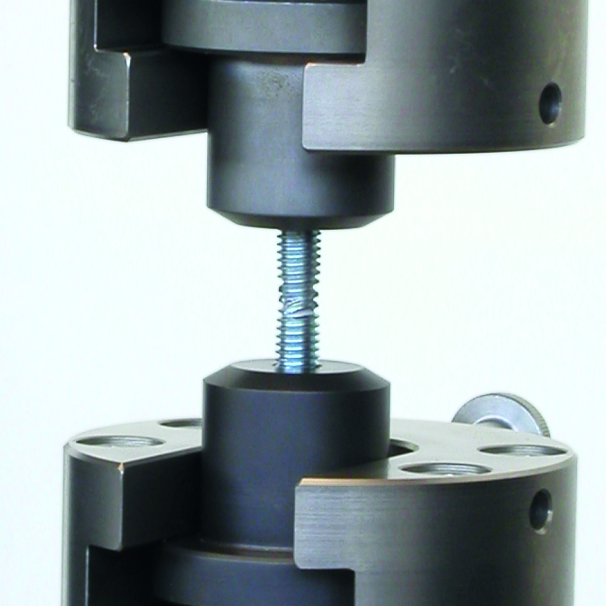
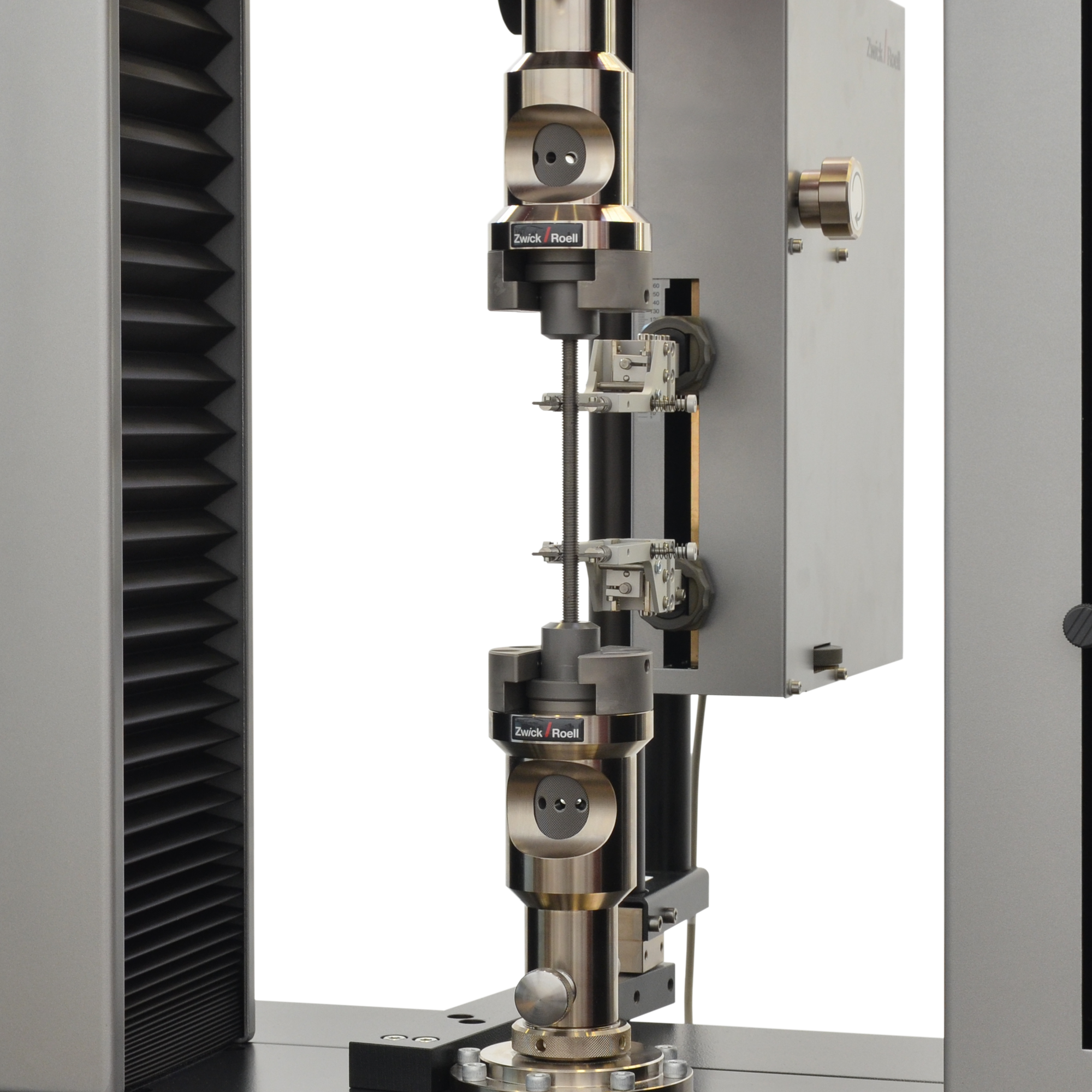
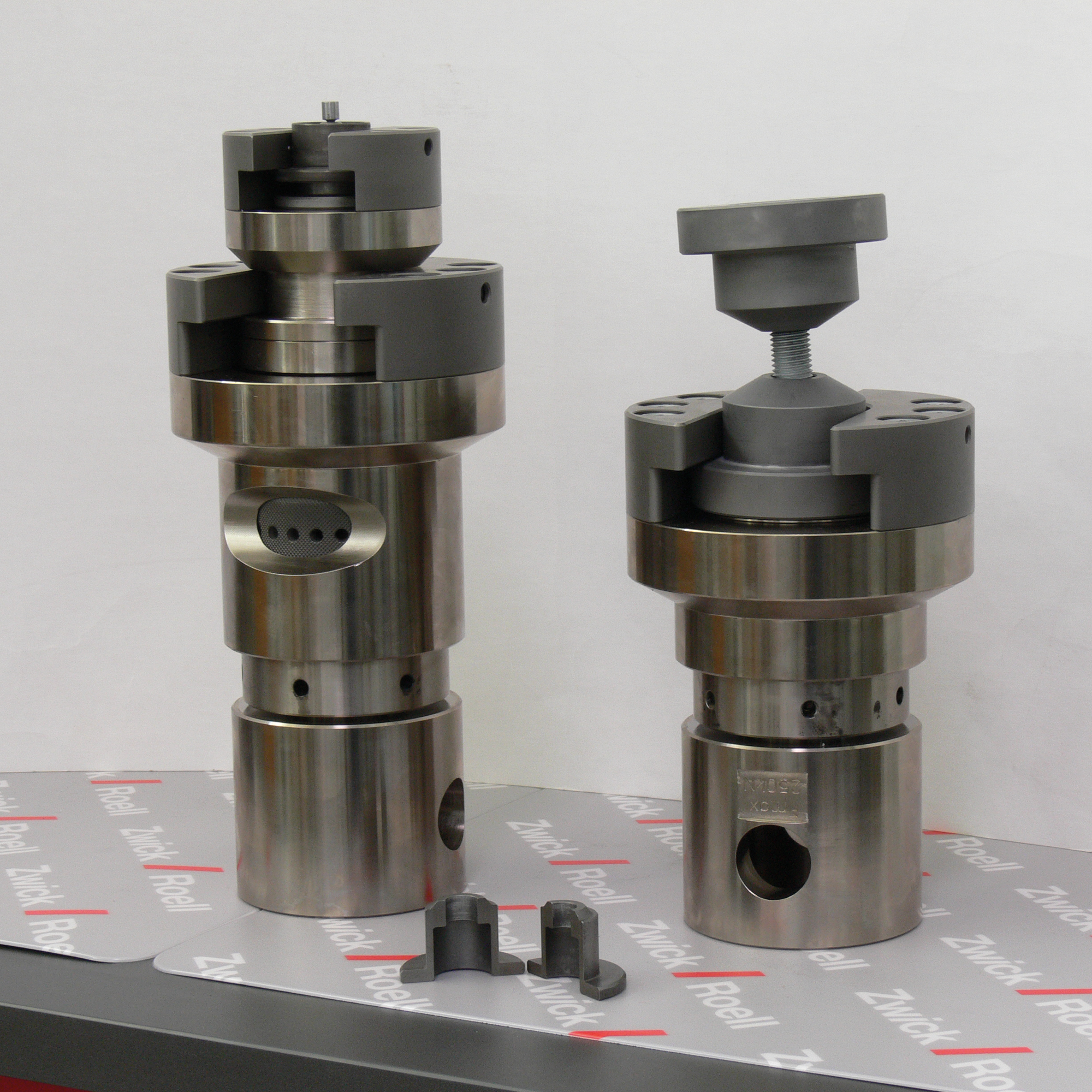
Specimen grips for screw, shoulder-headed and threaded-head specimens
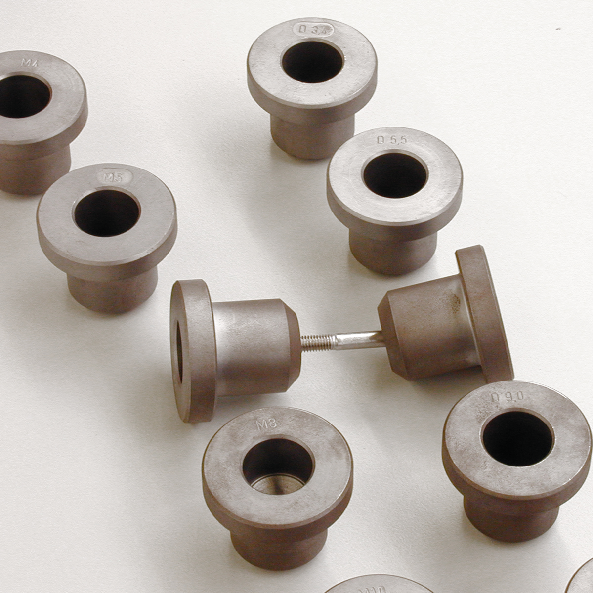
Form-fit force transmission via shouldered, screw or threaded head. The specimen, along with its corresponding holder, is inserted into the grips, which are freely accessible from the front, and is automatically centered in the tensile axis. The specimen grips are available with Fmax 50 kN, 250 kN, 600 kN and 1200 kN. Tests can be carried out on steel, non-ferrous metals and plastics in accordance with the standards DIN 50125, DIN EN ISO 6892-1, DIN EN ISO 4762, ISO 4017, DIN 6912, DIN EN ISO 898, ASTM E8 and others.
Various design details ensure an absolutely symmetrical flow of force:
- Specimen holder anti-backlash option ensures that the specimen is held securely, minimizing holder recoil at specimen break.
- all specimen holders completely surround the specimen. A support sleeve is placed around the split shoulder head specimen holder to prevent the the holders from spreading apart.
- Symmetrical bearing surfaces in the specimen grip: the specimen holders rest on two symmetrical contact surfaces in the specimen grip.
- The low height saves space in the test room
- Pure mechanical solution: they require neither a pneumatic control unit nor a hydraulic unit.


Specimen grips for ring specimens
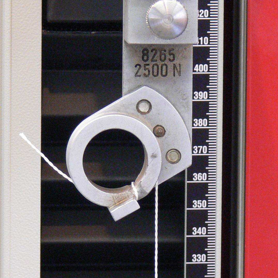
The specimen grip is suitable for testing elastomer ring specimens to DIN 53 504, standard ring 1 & 2. The specimen grip has horizontally mounted rollers. A spring hinge generates an autonomous rotary motion. This rotary motion facilitates form fitting force transmission. The spring hinge snaps out of position if the maximum permissible travel range is exceeded.
Advantages of the specimen grips for ring specimens
- The rollers rotate independently during the test by means of toothed belts or a roller spring belt and spiral drive spring
- Easy insertion of the specimen on the freely accessible rollers (up to max. 80 mm sample width)
- Protective device to protect against flying or bouncing specimen remains is available as an option
- Fmax: 2.5 kN
- Temperature range: -40 ... +150 °C
- The freely accessible rollers ensure easy specimen insertion

Specimen grips for tension springs
The specimen grip for tension springs is available in two versions, type I with Fmax 50 N for fine spring wires and type II with Fmax 10 kN. The force is transmitted via horizontal suspension bolts, which are available in various diameters (for a maximum spring wire diameter of up to 6 mm).
Advantages of the specimen grips for tension springs
- Easy mounting of the specimen on the mounting bolts, which are freely accessible from the front
- Suitable for temperature environments of -70 to +250 C°

Alignment fixtures
Precise axial alignment of the testing system test axis is a basic requirement for achieving reliable test results. Alignment must be performed with great care and precision, particularly when testing brittle materials such as glass, fiber composites, or certain metals. For this reason, ZwickRoell offers an alignment fixture for axial offset and angle correction.


Test tools
ZwickRoell test tools are characterized by a wide range of application possibilities. A large number of standardized solutions are available in terms of force range, opening width and temperature range.
- Compression tests
- Flexure test: 3-point flexure test kit and 4-point flexure test kit
- Plastics testing
- Testing of food and packaging
- Applications for the medical and pharmaceutical industry
- Composites Testing
- Testing of Paper, Cardboard, and Tissues
- Testing of Textiles
- Testing of Building Materials
- Spring testing

Specimen grip or test tool?
In addition to our specimen grips we also offer a wide range of test tools for special applications.
Read more about our specimen grips and test tools, or contact us directly.
Test tools Contact us