Biaxial testing
In the biaxial test—in contrast to the uniaxial tensile test—a specimen is loaded via two load axes.
The load can be applied through a torsional moment in addition to the tensile or compression test (tension-compression-torsion test). For this, the materials testing machine requires an additional torsion drive along with the drive through the crosshead.
For further material investigations under a biaxial tensile stress field, tests can also be carried out on cruciform specimens. For tests on this specimen shape, four test axes are required.
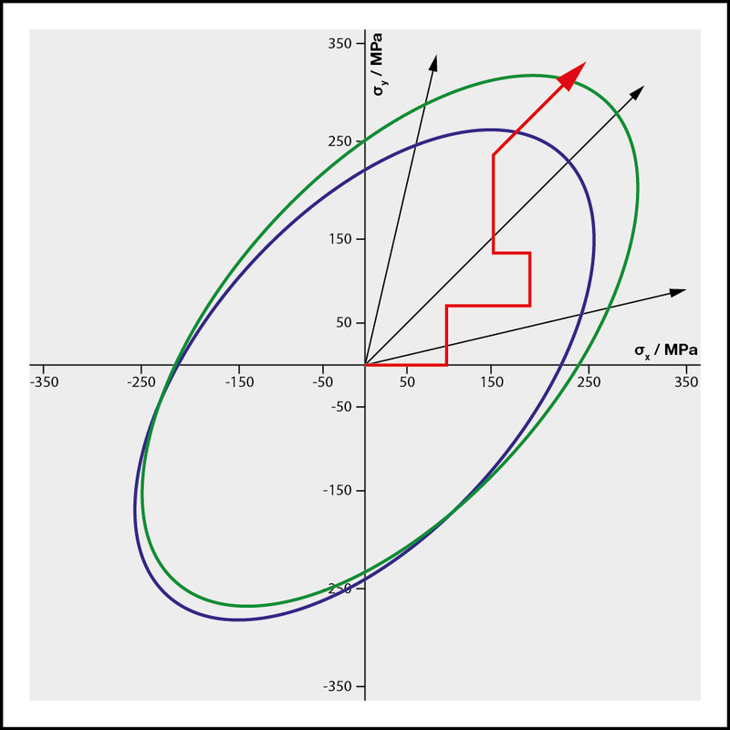
The additional test axes can be used to reproduce both constant stress ratios (linear stress path) and arbitrarily combinable stress paths (staircase approach).
Tensile-compression-torsion test Cruciform test Testing machines
Tensile-Compression-Torsion Test
The tensile-compression-torsion test is a multi-axis test method used in materials and components testing, which combines a torsional moment with a tensile test or compression test.
The use of a torsion drive causes the specimen to twist. Additional force application in tensile or compression direction causes different types of stress on the strength of the material.
The torsional moment (torque) Mt is calculated from the force F at the lever, multiplied by the length r of the lever used: Mt = F ⋅ r
The strain or load is measured by means of force and torque transducers.

Biaxial Tensile Test on Cruciform Specimen
A unique feature of materials testing is the biaxial tensile test, or two-axis tensile test. Increasing demands placed on materials mean that determination of material characteristic values via single-axis stress states are no longer sufficient. The cruciform test is used to generate tensile stress fields that arise when a cruciform specimen is under biaxial load.
To generate the biaxial tensile stress field, either four drive axes are required, which are individually controllable and adjustable, or two drive axes each in master-slave operation.
If in addition to strain measurement and control, mid-point control on the cruciform specimen is required, a solution with individually controllable and adjustable drive axes is absolutely necessary.
The biaxial tensile test is primarily performed in research and development to investigate defined stress values at the intersection point of the specimen. For the field of metals testing, there is an ISO-FDIS 16842 draft standard, which provides instructions on specimen design, test arrangement and test procedures.
The cruciform specimen is loaded in two directions (here vertical and horizontal). The arrows indicate the nominal stress. During the test, a particularly high level of material stress occurs in the corners of the cruciform specimen, which is designated as notch stress (area of stress concentration). The stress trajectories are shown as red lines.

Test strategies for uniaxial and biaxial load paths in cruciform tests
Again, the two load directions are displayed vertically and horizontally. The two test axes can be used to reproduce both constant stress ratios (linear stress path) and arbitrarily combinable stress paths (staircase approach).
The resulting test strategies are represented schematically in this diagram.
Optical strain measurement / strain control
Optical measuring systems are used for strain measurement in the biaxial tensile stress field. With an extended version of these measuring systems, control of the specimen midpoint in addition to strain measurement and strain control is also possible.
Here the specimens must be provided with appropriate markings, which the measuring system uses to record the displacements in the respective axis direction. Essentially four markings are required for the strain measurement/control.
If additional mid-point control is required, another mark is needed in the center of the specimen.


