Solenoid testing
Solenoid testing is used in research and development of electromagnetic actuators as well as in production processes or during incoming goods inspections at customer sites.
There are no international standards for solenoid testing that specify the performance and evaluation of characteristic tests on electromagnet components. The German DINVDE 0580 standard describes typical tests on these components. The tests also include an insulation test, measurement of the coil resistance and a conductivity test.
What are electromagnetic actuators? Test Force-stroke characteristic curve Force-current characteristic curve Current-stroke characteristic curve Testing machines
What are electromagnetic actuators?
Electromagnetic actuators are devices that convert electrical energy into mechanical energy. Electric current flows through an excitation coil of the electromagnet, thereby generating a magnetic field. This attraction force acts on the moving core and sets a mechanical movement into motion.
Due to their simple design and long service life, electromagnetic actuators offer a wide range of solutions for diverse technical requirements. Their applications range from automotive technology
and general mechanical engineering to hydraulic and pneumatic control units, precision engineering as well as housing technology and medical technology.
Key features include high operational safety, long service life, high efficiency and a good volume/performance ratio. A number of constraints form the specifications for the development of electromagnetic actuators: force and movement behavior dependent on the application and environmental conditions (temperature, climate, explosion protection), power supply (voltage, max. current) and energy dissipation (shutdown energy) as well as the available installation space.

Tests on electromagnetic actuators
Electromagnetic actuators are tested for different purposes.
- Tests in the field of research and development
In the development laboratory, the properties (characteristic curves) of the electromagnetic actuator simulated on the computer are verified using prototypes and sample series, and optimizations are carried out until the characteristic values of the magnet meet the requirements. This is also where the test sequences and parameters used for quality assurance purposes are normally determined. - Production-integrated 100% testing by electromagnetic actuator manufacturers
In production, the quality of each production process, each installed assembly (e.g. excitation coil) and the quality-determining properties of the end product must be verified by standardized tests. - Incoming goods inspection at customer sites of solenoid manufacturers
Random testing of the required characteristic values as well as acceptance of initial samples.

Force-stroke (F/s) characteristic curve test
The force-stroke characteristic curve (F/s) ensures that the nominal solenoid force is reached at a specified stroke and fixed rated excitation current (plus or minus the tolerances).
The force-stroke characteristic curve is tested when using proportional or switching solenoids. It represents a function test on electromagnetic actuators and is usually the final test. Basic function properties can be ascertained from the characteristic curve. The force-stroke characteristic curve provides information as to whether the actuator is applying the required force inside its operating range at a fixed current. The hysteresis provides information about friction resulting from the quality of the mechanical parts.
Test procedure
- The component is inserted in the clamping fixture and electrically connected.
- The excitation coil is energized with its rated current. The armature moves to its end position.
- The testing machine moves the die with Vv speed to a predefined preload to find the travel zero-point. The stroke (s) measurement channel is set to zero and the measured value acquisition is switched on. The force, stroke and time (optionally current) measurement values are recorded.
- The armature is then pushed out of its end position at a specified test speed and moved back to the end position. If the “stroke measurement” option is selected in the test sequence, the armature is moved to block force in the last phase at creep speed up to the rear end stop.
- A variety of test strokes can be selected. Each test stroke is assigned an excitation current value, which is automatically set through our testXpert testing software or manually set by the operator. The operator is guided by corresponding software dialog boxes.

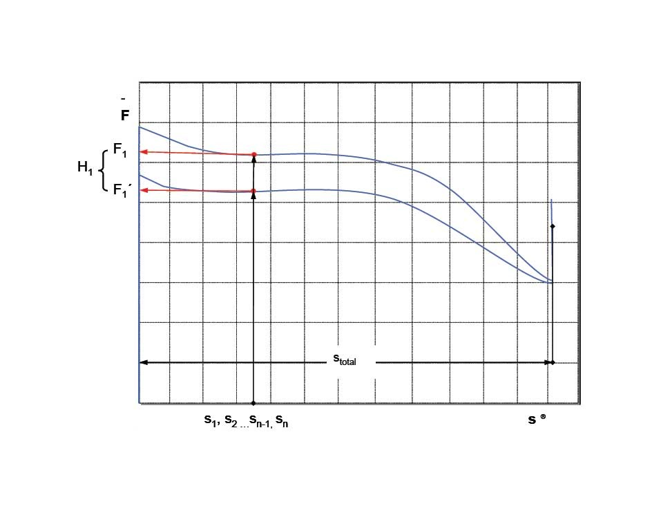
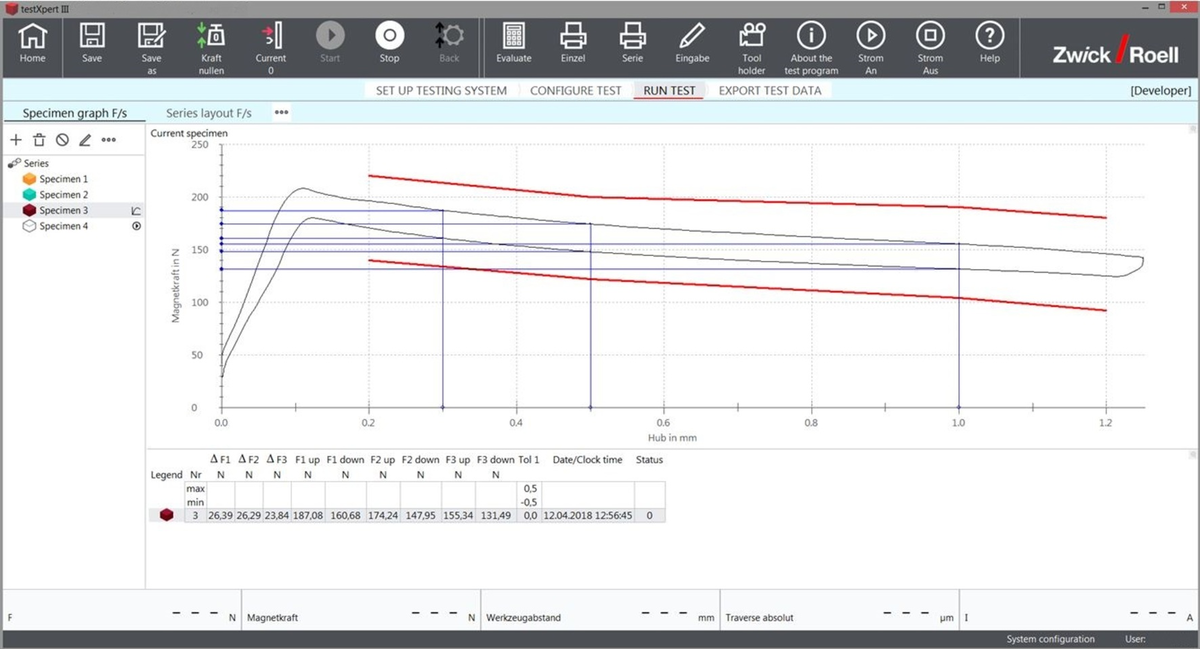
Characteristic values on the force-stroke diagram
For the reference values stroke S1 to Sn, the forces F1 to Fn are determined in both directions of movement of the armature. To obtain the hysteresis at the stroke reference values, the difference of the two forces lying at the same stroke reference is determined. Optionally, the largest hysteresis Hmax within a specified range and the stroke length can be determined.
By setting up to four tolerance ranges, the upper and lower limits can be set for the solenoid force characteristic curve. This can, for example, be used for good/bad determination in the production control process.
Force-current (F/I) characteristic curve test
The force-current characteristic curve test ensures that the required force is achieved at a specified current for a fixed stroke.
The force-current characteristic curve is predominantly tested for proportional solenoids and provides information as to whether the actuator is applying the required force inside a current range at a defined armature position. The ideal characteristic curve has a linear relationship between force and current around the operating point.
Test procedure
- The component is inserted in the clamping fixture and electrically connected.
- The excitation coil is energized with a low current, so that the armature moves to its end position.
- The testing machine moves the die with speed Vv to a predefined preload to find the travel zero-point. The stroke (s) measurement channel is set to zero. The power is switched off.
- The testing machine moves the armature of the unexcited solenoid to a defined stroke position. The measured value storage function is switched on. The force, current, stroke and time measured values are recorded.
- The current is ramped up to nominal current at a defined current-increase rate and ramped back to current zero at the same rate.

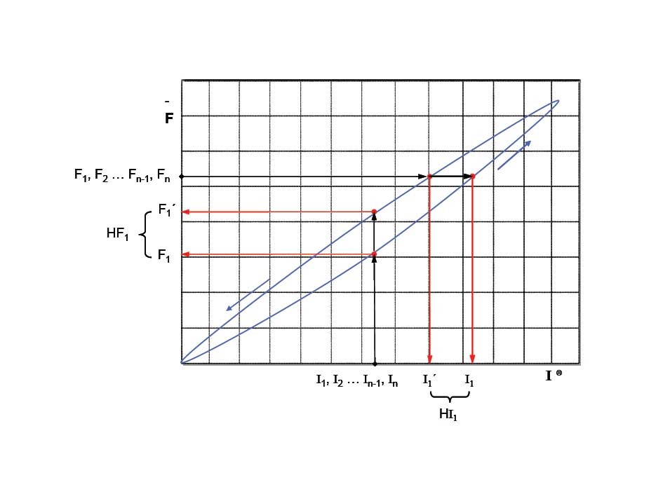
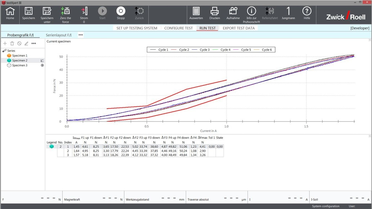
Characteristic values on the force-current diagram
For the reference values current I1 to In, the forces F1 to Fn are determined in both directions of movement of the current. For reference values F1 to Fn, currents I1 to In are determined. To obtain the hysteresis at the electrical current reference values, the difference of the two forces lying at the same electrical current reference is determined.
By setting up to four tolerance ranges, the upper and lower limits can be set for the solenoid force characteristic curve. This can, for example, be used for good/bad determination in the production control process.
Current-stroke characteristic curve test
The current-stroke characteristic curve is tested when using proportional or switching solenoids. The solenoid, which is supplied with a given current, presses against a precision spring with linear characteristics or against a weight and must produce defined strokes.

Related testing machines for solenoid tests
- Electromechanical servo testing actuators are especially suited for the integration of solenoid testing in fully automated, hybrid and manual assembly lines as in-line or end-of-line test modules.
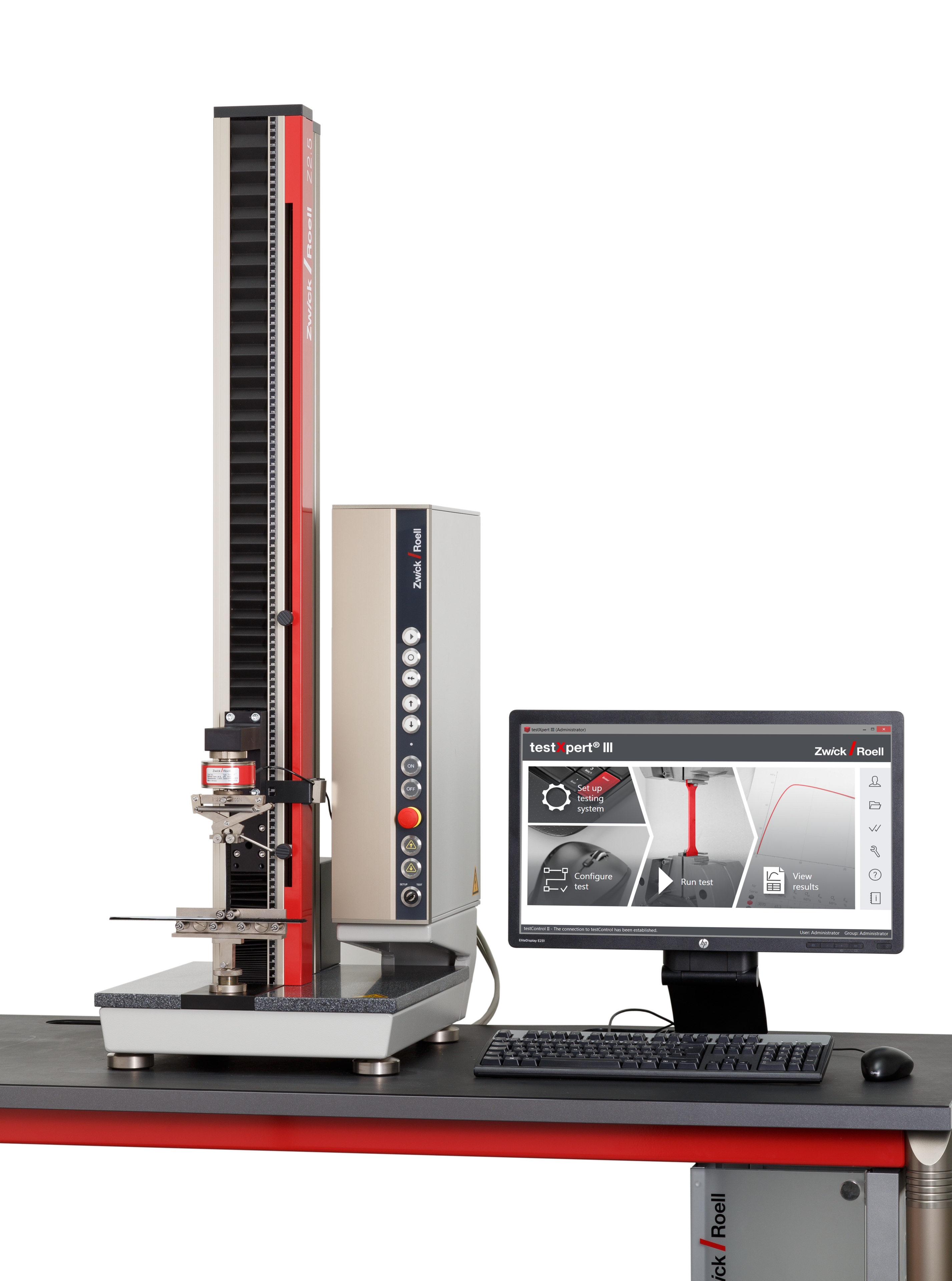
- The zwickiLine (single column frame) is used as a stand-alone test rig in the area of development as well as in manual or hybrid assembly lines.
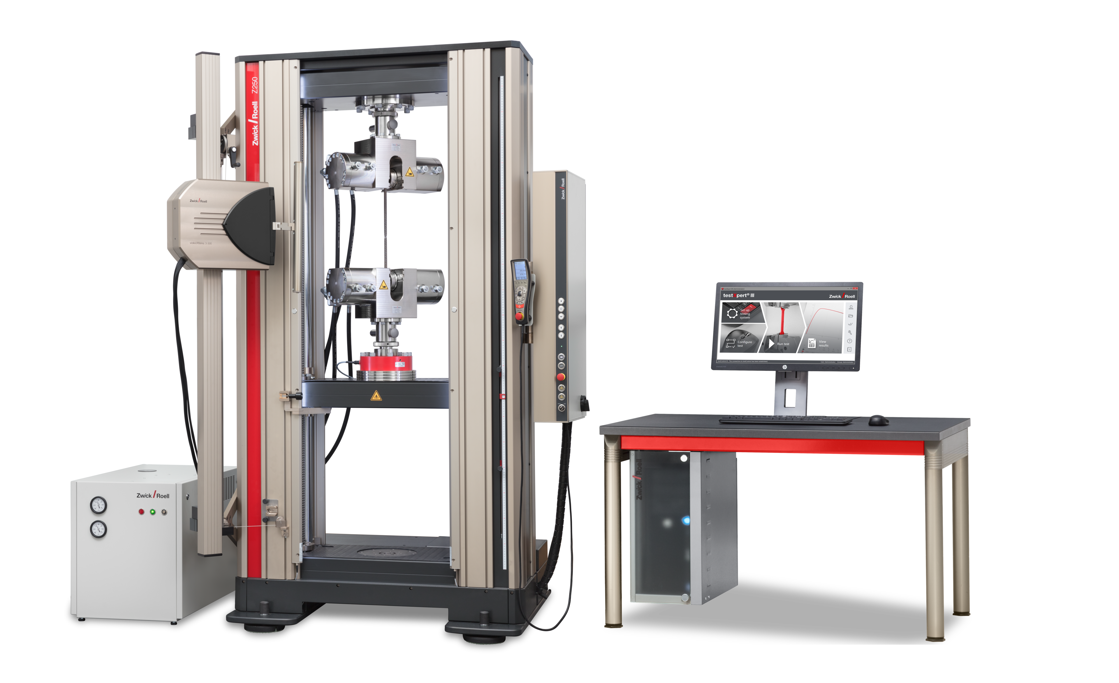
- The AllroundLine is a two-column load frame machine and is used for large forces in both development and production for solenoid testing.

Electrical current controllers
To control the solenoid with an excitation current, ZwickRoell uses PWM or DC current controllers. Customer-supplied current controllers or control cards with control voltage input can also be integrated into the testing system and controlled by the materials testing machine’s PC.
The control process normally uses an analog signal (0-10 V), which is output via an I/O module. This I/O module can also generate current ramps. Parameterization takes place within the testXpert testing software.
testXpert testing software for solenoid testing
With testXpert, you have access to a proven testing software that makes it easy to perform complex force-stroke and force-current characteristic curve tests. The customer has free, universal access to test sequence parameterization, including the number of cycles, working stroke, speed, hold time, block force, solenoid current and upper and lower limit tolerance ranges.
With the additionally expandable “free stage definition” option, the user can freely parameterize test sequences.